
|
Other forms of gravity-type VA meters may incorporate a piston or vane that responds to flow in a manner similar to the float's behavior. All these devices can be used to measure the flow rates of most liquids, gases, and steam. There are also similar types that balance the fluid flow with a spring rather than gravitational force. These do not require vertical mounting, but corrosive or erosive fluids can damage the spring and lead to reduced accuracy.
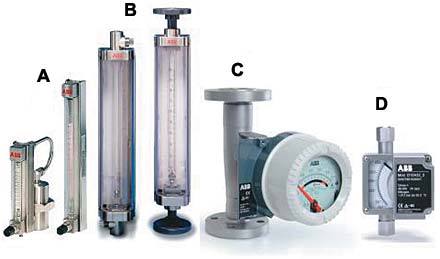 Typical rotameter types widely used in the process industries include two low-capacity meters often used as purge meters (A). (Note the optional scale lengths); higher capacity, "standard" meters (B), shown here with female threaded connections (left) and screw-on pipe flanges (right); metal tube or armored rotameters for higher flow capacities (C) and for low flows including purging (D). |
The term rotameter derives from early versions of the floats, which had slots to help stabilize and center them and which caused them to rotate. Today's floats take a variety of shapes, including a spherical configuration used primarily in purgemeters (which will be discussed later on). The materials of construction include stainless steel, glass, metal, and plastic.
| (1) |
where:
| Q | = volumetric flow rate, e.g., gallons per minute |
| k | = a constant |
| A | = annular area between the float and the tube wall |
| g | = force of gravity |
| h | = pressure drop (head) across the float |
With h being constant in a VA meter, we have A as a direct function of flow rate Q. Thus, the rotameter designer can determine the tube taper so that the height of the float in the tube is a measure of flow rate.
Rotameter Design Components
The two basic components of every rotameter are the tapered metering tube and the float. Tube sizes vary from 1/16 to 4 in., with a 1/8–2 in. range being the most common. Of course, each model has limitations as to capacity, temperature, pressure, and, in the case of liquids, viscosity.
Glass Tube Rotameters. With a tapered metering tube made of borosilicate glass, this was the original rotameter. Introduced in the mid-1940s, it is referred to as a "general-purpose" rotameter. Because the float is normally visible in the tube, the
|
Glass tube rotameters are typically used for simple but reliable indication of flow rate with a high level of repeatability. Alarm contacts can be easily added to provide high-, and/or low-flow signals, in which the contact is activated as the flow rate either drops below or rises above the set point.
Linear scale graduations can be an arbitrary 0%–100% for the meter range. Calibration can be direct reading in terms of a specific gas or liquid, or a graph that plots meter readings vs. flow rates in terms of the fluid being measured. Such graphs make it easy to adapt a meter to handle fluids other than those for which it was bought; changeover is simply a matter of having a different conversion chart designed for the new fluid.
The meter assembly's metal body is rigidly constructed to maintain tube alignment. The various types of end fittings provide process pipe connections, either threaded female or flanged. O-rings or packing glands at either end of the tube seal it to the end fittings. Some designs provide for easy removal of the glass tube for cleaning or range change without pulling the meter from the pipeline.
Metal Tube Rotameters. These devices, also known as armored meters, are designed for applications where the temperature or pressure exceeds the limits of glass tubes. Flow rate is indicated by a pointer on an indicating scale by means of a magnet inside the float, magnetically linked to the pointer. Designed for indication only, metal tube meters require no external source of electric power. They may also be specified in applications requiring remote transmission of the measured flow rate, a feature not generally available with glass tube meters.
Available in a variety of tube and float combinations, metal tube meters are generally made of corrosion-resistant type 316 stainless steel. They are well suited to measuring steam flow where conditions or regulations prevent the use of glass, and useful as well where the nature of the fluid would preclude reading a float position. The meter shown here is constructed of all 316-Ti stainless steel. The equally corrosion-resistant float is magnetically coupled to the scale pointer and can also be coupled to high- and/or low- flow alarms or to an electronic converter that generates a 4–20 mA signal for transmission over a 2-wire cable to a remote indicator, recorder, or controller.
The signal can also provide a local digital display, HART protocol output, and scaled pulse output for flow totalization. The HART output permits remote communication over the same 2-wire cable that carries the flow rate signal. This provides remote digital access to the meter and a link to plantwide control systems.
A low-capacity design is available for low flow measurements at high pressure and temperature, or where the use of glass is restricted for safety reasons. Its integral needle valve and constant-flow, differential pressure (dp) regulator are useful when it is used as a purgemeter.
This small armored meter can also incorporate contacts for maximum and/or minimum alarms and a 4–20 mA analog output. Their NPT process connections are available in 1/8, 3/8, 1/2, and 1 in. sizes.
Plastic Tube Rotameters. Plastic tube rotameters can be an entirely suitable, very cost-effective alternative to glass or metal meters for a wide variety of fluid measurements. One popular model is made of a single piece of clear acrylic that is practically unbreakable in most industrial process applications. Often used as a purgemeter, this type is a low-cost, reliable solution for many OEM applications.
Float Designs. The float in small purgemeters is usually a ball made of black glass, stainless steel, sapphire, Carboloy, or tantalum. For larger sizes in both glass and metal tubes the float is generally machined from corrosion-resistant materials with variations to suit the application. Floats are available in a variety of shapes and materials, with varying densities that can be used to change the meter's range and to resist corrosion from the measured fluid. While Type 316 stainless steel is common, floats are also available in tantalum, Hastelloy C, Monel, Teflon, and PVC.
Use in an Orifice Bypass
To cost-effectively handle larger flow rates of liquids or gases, a rotameter can be installed in a bypass line around an orifice plate. The differential pressure produced by the orifice causes a relatively low flow through the rotameter that can be a measure of flow through the main pipeline. Key benefits include:
- Usefulness where the measurement must be made in a hazardous or remote area, or where electric power is either not available or would be potentially dangerous
- Rangeability that can be 121/2:1, as compared to 4:1 for dp meters
- Scale readings that can be graduated in direct units for flow in the main pipeline
- Changing the range or cleaning the tube without disassembling the meter or removing it from the bypass line.
Purgemeters—A Major Class of Rotameters
In terms of total worldwide rotameter sales, the models classified as purgemeters dominate the field today. According to the ISA, a purgemeter is "designed to measure small flow rates of liquids and gases used for purging measurement piping." As can be seen from the five application examples below, however, purgemeters are sometimes used for other tasks. All purgemeters have one important characteristic in common: they facilitate setting and accurately controlling the low flow rates involved. For water, the rate is typically well under 1 gpm; for air, it is <2 scfm.
Purgemeters offer the basic benefits of rotameters. For purging applications, considerations of special note include:
- A constant-flow dp regulator is used to maintain purge flow rate at a desired level. The regulator may optionally be specified as part of an integral assembly with the meter.
- An optional inclusion of a needle valve in the purgemeter makes it convenient to set the desired purge flow rate.
- A simple indicating purgemeter requires no external power source.
- The meter is inexpensive and compact enough for OEM mounting on either a panel or the equipment itself.
- Purgemeters come in both glass and metal tube variations and can be equipped with high- and/or low-limit alarms.
Five Sample Applications
Bubble Tube Purge for Liquid Level Measurement. Bubble tubes are a common and inexpensive way to measure liquid level by measuring hydrostatic head, which is density dependent. Figure 2 shows systems designed for open vessels and for closed vessels under pressure. Each requires only one purgemeter with a pressure regulator.
 Figure 2. Bubble tubes determine liquid level by measuring the hydrosstatic head, which is density dependent. The principle works for both open and pressurized closed vessels. |
In an open vessel, at very modest cost, a simple indicating pressure gauge can measure the backpressure from the dip tube. Another technique is to use a pressure recorder, with or without control. Yet another is the widely used dp transmitter, with back pressure connected to the high side and the low side left open to atmosphere.
A pressurized vessel requires two dip tubes with one above the maximum level, exposed to the vessel pressure and connected to the low side of a dp transmitter. The other dip tube, extending down to near the bottom of the vessel, thus can be a measure of head due to liquid level. The effect of operating pressure that may vary is eliminated.
The purgemeter is commonly used in this application, with certain precautions that apply to density measurement such as keeping the flow rate low enough to ensure there is no incorrect increase in back pressure. The air or gas supply pressure, however, must exceed the maximum line pressure by ~10 psi.
Purging Pressure Taps of Orifice Flowmeters. A very common method of measuring flow rate requires the creation of a differential pressure across an orifice plate installed in the flow line (see Figure 3).
 Figure 3. Constant-flow purgemeters prevent a pressure-sensing device from fouling or plugging. |
A dp transmitter is generally used to measure the pressure differential by means of pressure tap lines connected upstream and downstream from the orifice. The supply pressure should exceed line pressure by ~10 psig.
If the measured liquid or gas is the least bit corrosive or dirty, or contains solids, the system designer should use a gas or clean liquid to purge the pressure tap lines. To accomplish this, a pair of purgemeters, often with pressure regulators, feeds the purge fluid into the pressure tap lines. When an orifice meter is to measure gas flow, the tap is installed above the orifice. The purge fluid is usually air or an inert gas such as nitrogen.
For liquid flow, the taps are positioned below the orifice and the purge fluid is generally water. For heavier petroleum products, the purge may be kerosene or some other clean, light hydrocarbon.
Continuous Forced Lubrication of Bearings. The bearings on heavy, rotating equipment require continuous, forced lubrication to extend their functional life and reduce machine downtime. A purge-type flowmeter (see Figure 4) can be used to set the flow rate of lubricant as it is pumped to the bearings.
 Figure 4. Expensive equipment can be made fail safe by adding an alarm to the rotameter that monitors lubricant flow. |
An electrical alarm is often added to the meter to alert the operator should the flow rate fall too low. An electrical alarm is a positive, fail-safe device in that it measures flow directly rather than inferentially. For this application, the rotameter should be calibrated for the higher viscosity of the lubricating oil.
Bubble Tube Purge for Density Measurement. The density of a liquid is defined as mass per unit volume (e.g., grams per cubic centimeter or pounds per cubic foot) at a stated temperature. One of the oldest and simplest ways to measure density is by measuring the hydrostatic head in a tank (see Figure 5).
 Figure 5. One type of continuous liquid density measurement system incorporates two dip tubes, a constant-flow purgementer, and a dp transmitter. |
Two bubble tubes are immersed in a tank at different depths. The differential back pressure of the purge gas in the two tubes, ![]() P, is a measure of the head, which in turn is a function of liquid density,
P, is a measure of the head, which in turn is a function of liquid density, ![]() , and the difference between the depths of the two tubes (L1- L2):
, and the difference between the depths of the two tubes (L1- L2):
| (2) |
A pair of purgemeters, typically equipped with pressure regulators, can ensure a small, uninterrupted flow of air or inert gas into the bubble tubes. The flow rate must be low enough that pressure drop through the purge piping does not increase head back pressure. The pressure differential can be measured with a dp transmitter, enabling remote transmission and automatic control.
Use of Purgemeters with Gas Analyzers. Many types of gas analyzers require a controlled, small rate of sample flow into the analyzer. Some analyzers also require the introduction of modifying gases with the sample. Since the flow rates involved are usually very low, purgemeters are often an integral part of the analyzer cabinet.
Some Advice on Choosing a Rotameter
Assume you believe a rotameter may be a good solution to your flowmetering problem. The benefits it offers are appealing and a check of the guidelines in the sidebar "Guide to Deciding on a Rotameter" and Table 1 indicates
|
- Fluid type. The more information on the nature of the fluid, the better. Is it liquid, gas, or steam? If it is highly corrosive, give its chemical name, e.g., sulfuric acid, and its concentration. Are there entrained solids? And so on.
- Fluid density. Give specific units, such as grams per cubic centimeter, at a specified operating temperature. Alternatively, you can specify fluid-specific gravity, which is the ratio of the fluid density to the density of water (in the case of a liquid) or to that of air (in the case of a gas), at a specified temperature.
- Fluid viscosity. Again, use specific units such as centipoises or centistokes at a specified operating temperature. (See the text box, "The Viscosity Immunity Ceiling.")
- Operating and maximum temperature and pressure. This information is a must for gas applications.
- Flow rates. What are the minimum and maximum?
- Required functions. What tasks will your system be expected to do? Will you need to incorporate indicators, control devices, alarms, or remote transmission capabilities?
- Indicating scale type. Do you want your readout in percent, direct reading, or some other format?
- Materials of construction. Don't forget system components such as end fittings, O-rings, regulators, and valves.
- Valve requirements. Will you need, for example, a needle valve on the flow inlet or outlet?
 Screen 1. The counter/display logic all fits inside a single user-configurable cPLD. Programmability allows designers to specify the logic they want, instead of merely settling for what is available. |
Sizing a Rotameter
Most manufacturers have taken all the factors and data involved in sizing a rotameter and developed a sophisticated software program available on one CD for use on a PC. One such program can be downloaded from ABB's Web site (see Screen 1).
These programs include volumes of pertinent data that will guide you through the sizing process. For example, assume you need to measure methane gas at a rate of 300 scfm. You can access a reference table that lists the properties of all major gases. You enter the necessary sizing data for methane such as operating pressure and temperature, maximum flow rate, and meter type such as glass or metal tube.
The program then suggests that to meter methane under the conditions indicated, a 2 in. meter with a specified type of glass tube and float will do the job and the flow range will be 25–335 scfm. If you prefer a metal tube, all you need do is click on Metal Type on the screen. This new tool does away with having to convert the actual maximum flow rate to a standard rate based on the water or air equivalent, along with density and viscosity variables and their requisite equations.
Summary
This article has addressed the operating principle and advantages of the rotameter, along with some basic information about their applications. In addition to being the most economical, these devices are still the most practical solution to many flow measurement problems.
For Further Reading
Dictionary of Measurement and Control: Guidelines for Quality, Safety, & Productivity. 1995. 3rd Ed., Instrument Society of America.
Dolenc, John W. Jan. 1996. "Choosing the Right Flow Meter." Chemical Engineering:22-32.
Handbook, Process Measurement and Analysis. 1999. 3rd Ed., Bela G. Liptak, ed., CRC Press.
"Rotameters/Variable-Area Flowmeters." Sept. 1996. Measurements & Control.
Spitzer, David W. 1990. "Variable Area Flowmeters," Industrial Flow Measurement, ISA Resources for Measurement and Control Series.
| |||||||||||||||||||||||||||||||||||||||||||||||
|