Summary
Head-up display (HUD) technology is one of the largest growth areas in the automotive market, and standard measurement criteria are rapidly being defined to evaluate HUD performance for quality and safety. This article introduces methods for meeting the requirements of the new SAE J1757-2 standard and outlines the advantages of automated measurement systems.
Introduction
Head-up display (HUD) technology has a key focus on increased passenger safety through improved vehicle operations and operator awareness. According to research, HUD technology has a compound annual growth rate (CAGR) of 21.67%, and is expected to achieve a market size of USD 1.33 Billion by 2021.1

position, color, brightness, and clarity of HUD images augments the operator experience and limits error that may cause distraction.
The safety implications of HUD have guided manufacturers of automotive test and measurement equipment to partner with the Society of Automotive Engineers (SAE) Committee to define standard measurement criteria to assess the quality of HUDs and their compliance in accordance to standards SAE J1757-1 and ISO 15008. The new standard (SAE J1757-2 “Optical Metrology for Automotive HUD” 2), to be published in late summer 2017, provides a methodology for optical measurement geometries and requirements for measuring vehicle HUD performance. These measurements require an optical measurement device or meter with NIST-traceable calibration, which is to be positioned at several measuring points within the operator’s eye ellipse area (to account for the scope of potential viewing angles), for measurement of the above criteria.
Referenced in the SAE J1757-2 standard as a primary solution for HUD testing, automated imaging photometers and colorimeters provide NIST-calibrated optical measurement technology to capture absolute measurements of luminance, chromaticity, contrast, object location, and distance. These solutions offer several advantages in the application of automated visual inspection to acquire the necessary data for SAE HUD compliance with greater speed and ease as compared to alternative systems.
SAE Measurement Criteria Simplified by Automated Imaging Systems
Calculating Object Distance and Location
SAE J1757-2 specifies that an optical measurement system for HUD evaluation must measure the “real distance” between the nominal eye center (the operator’s nearest visual focal point) to an opaque monocolor paravan (surface) positioned at the perceived distance of the projected virtual image. In standard measurement systems, distance measurements from near to far are found using the camera’s focal distance to evaluate the points along the horizontal plane where the camera can image objects in focus. The calculations required to convert focal distance to real distance units can be performed manually, but there are also measurement systems that can perform this conversion automatically. Such systems provide focal-to-real distance conversion using built-in software algorithms, enabling operators to display measurement data in real distance units in the system’s software results.
Performing Multiple Measurements
To account for multiple potential viewing angles from the vehicle operator to the HUD projection, as well as to average out the margin of error, SAE J1757-2 requires that at least three measurements be taken at different locations on the paravan to determine the relative virtual image distance. Using standard fixed-lens measurement systems, the process of measuring multiple points is time-consuming and arduous. Alternatively, imaging systems with electronically-controlled lenses greatly improve the speed and accuracy of measurements at multiple angles, positions, and distances. These lenses can be remotely adjusted to ensure proper focus and aperture settings for image location at the paravan, or on an infinite plane, as shown in the examples below.

Measuring Luminance of Colored Objects
According to SAE J1757-2, minimum luminance thresholds must be achieved to ensure visibility of the HUD’s virtual images superimposed upon the real-world environment in any ambient lighting condition (daylight or night). However, measuring the luminance of every virtual image in a HUD projection means accounting for a wide range of object shapes, sizes, colors, and locations.
This process requires multiple steps when using a measurement system that locates objects based on static points of interest (POI). For each object projected into the HUD, a static POI system finds the target object within the inspection area by looking within a static POI window drawn in the software. The imaging system will use this POI to determine which set of pixels in the image to apply luminance measurements.
If the projected object falls outside of this POI, an inaccurate luminance measurement may result. Additionally, as projections change or new virtual images are introduced on the display, new POI must be drawn to encompass each new object before luminance measurements are acquired.

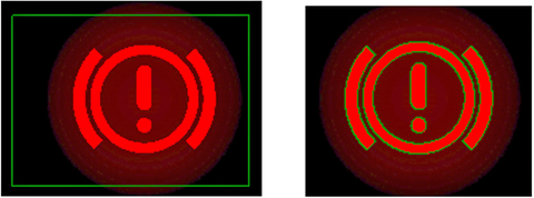
Some advanced light measurement systems provide software capability that fully automates the process of POI-setting for multiple and even unpredictable objects in a projection. A software feature called Auto-POI (Automatic Points of Interest) in the latest imaging colorimeters, for instance, creates dynamic POI windows that automatically adapt to object pixels that fall within a defined color tolerance. A manufacturer may wish to evaluate the luminance of all red objects in a projection at once.
For this measurement, the manufacturer would set minimum and maximum CIE color coordinates (Cx, Cy) in the software to encompass the range of red values represented in the target set of objects. Leveraging Auto-POI, the software would then “snap to” any set of continuous red pixels that match the defined criteria, creating accurate measurement regions regardless of object shape, size, or location. Even as new projections are introduced, objects matching the defined color tolerances in Auto-POI would be captured and measured for luminance values at once and on demand.

Auto-POI (Automatic Points of Interest) adapted to an object based on color tolerances.
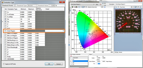
Auto-POI allows multiple color sets to be programmed at once, enabling manufacturers to measure all objects in an image simultaneously, regardless of color. Additionally, when specifying color value tolerances, the manufacturer has the option to enter CIE coordinates as data, or to draw color regions on a CIE color chart (using the cursor to create an ellipse, rectangle, or polygon) to specify POI tolerances.
These features fully automate the measurement process, offering the manufacturer a “point-and-shoot” method for luminance measurement once all object colors have been defined. Combining Auto-POI with an electronically-controlled lens offers the ultimate flexibility in object location and evaluation for nearly instant data acquisition at each defined measurement point.

color chart to define Cx, Cy tolerances for colored objects that should be included in the measurement POI set.
Multi-Measurement Test Sequencing
Per SAE J1757-2, a HUD measurement system must perform luminance measurements on checkerboard images with alternating patterns to determine virtual image contrast for white and black projections in ambient light. The system must also determine luminance uniformity and non-uniformity of the virtual image, as well as chromaticity as compared to the target virtual image. Additional measurements must be taken to determine image distortion and aberration, as discussed above, to ensure accurate image shape and location as compared to the target virtual image.

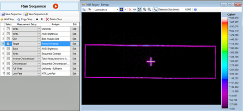
to MTF line pair analysis, to perform multiple measurements of the HUD projection at once.
The complexity of performing all measurements required for complete HUD evaluation is dependent not only on the flexibility of the hardware, but also on the limitations of the measurement software. The complete measurement process can be extremely time-consuming if the chosen system employs software developed to run a single measurement at a time, or, if the system employs multiple software packages engineered for unique measurement applications. For example, applications employing a photometric system for light measurement, with an additional visual inspection system capable of object position measurement.
Alternatively, automated test sequencing software may be applied to enable several measurements to be performed in rapid succession using a single system. Test sequencing software programs allow distinct measurement criteria, POI, and inspection tolerances to be programmed into a series of separate steps within one software environment and then run as a multi-part evaluation of the HUD. This allows luminance, chromaticity, location, and distance measurements to be performed to measure multiple aspects of the HUD automatically without reprogramming the measurement software for entirely new criteria or system replacement.
Conclusion
With the finalization of the SAE J1757-2 standard coupled with the rapid growth of the HUD market, the demand for efficient measurement systems is destined to increase to ensure automotive manufacturers and suppliers achieve compliance and remain relevant and competitive in their industry. As SAE standard compliance becomes the baseline qualification for HUD selection, the competitive advantage for manufacturers will be the speed and efficiency to produce quality products that ensure optimal value of their technologies. Automated HUD measurement systems that include imaging photometers or colorimeters with advanced test sequencing software greatly reduce HUD evaluation time, enabling production-level measurement, ensuring compliance, and limiting cost and time to market.
References
1 MarketsandMarkets. (2016, April). Report Code AT 2973: “Automotive Head-up Display (HUD) Market by HUD Type (Windshield & Combiner), Application (Premium, Luxury & Mid Segment Cars), and by Geography (Asia-Oceania, Europe, North America & RoW) - Industry Trends and Forecast to 2021”.
2 SAE International. (2015, May). Standard J1757/1_201505: “Standard Metrology for Vehicular Displays”. http://standards.sae.org/j1757/1_201505/
About the author
Matt Scholz is the International Senior Business Advisor for global automotive projects at Radiant Vision Systems. Having spent close to 10 years working on automotive metrology applications, Matt has a strong and fundamental understanding of the growing challenges faced by this industry for increased control in lighting and illuminated components, cross-component harmonization, display quality, and manufacturing integrity. Matt has worked with all levels of the automotive supply chain, from Tier 1,2, and 3 vendors to major brands and OEMs worldwide. As the company’s dedicated liaison for the industry, Matt strives to build on Radiant’s success by sharing his expertise on measurement equipment and providing a consultative approach to system integration for varying automotive applications.
Contact Info:
Radiant Vision Systems, LLC
+1 (425) 284-0152