

Process control decisions are often driven by one or more critical parameters, such as conductivity, pH, turbidity, total suspended solids, dissolved oxygen and chlorine. Analytical sensors for these parameters are widely used in the water and wastewater, chemical, food and beverage, pharmaceutical and other industries. This article provides for a basic understanding of the application, theory, installation and maintenance requirements for these common analytical sensors.
Conductivity Measurements
Conductivity is the ability of a liquid to conduct electricity based on the ionic concentration of a solution. In food and beverage, for example, a conductivity measurement is frequently used to confirm clean in place (CIP) solution concentration and to optimize the CIP cycle. The conductivity measurement monitors the concentration of solutions in the return line, and measures the temperature with an integral temperature sensor. Together, the conductivity sensor and its integral temperature element provide critical data used to detect, control and monitor the CIP process including product, rinse water and CIP solution transitions.
In the pharmaceutical and food and beverage industries, requirements for hygiene and cleanliness are critical. Water for injection (WFI) and other water purification systems use conductivity as a means to detect contamination.
Three types of conductivity analyzers are most commonly used:
Two Electrode: Contacting, two electrode sensors (figure 1) use alternating voltage applied to the medium. The resulting current flow through the medium is then used to calculate the process conductivity value according to Ohm's law. Two electrode sensors must be selected with the appropriate cell constant to avoid linearity issues associated with polarization. Lower cell constants are used in low conductivity applications and higher cell constants in high conductivity processes. The dynamic range of contacting sensors and their resistance to fouling are very limited.
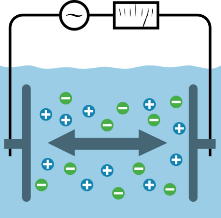
Fig. 1: Two-electrode conductivity sensor.
Generally, two-electrode sensors are used in processes where fouling is unlikely and the operational conductivity range is limited. When properly applied, operated and maintained, the two-electrode sensor is the most accurate sensor type in low conductivity processes.
Next page
Inductive: Inductive sensors (also called toroidal, electrodeless and non-contacting), induce an electrical current into the medium via a primary coil. A secondary coil receives an electrical current flow that is proportional to the conductivity of the solution (figure 2). Inductive sensors have a wide dynamic range and are highly resistant to fouling.
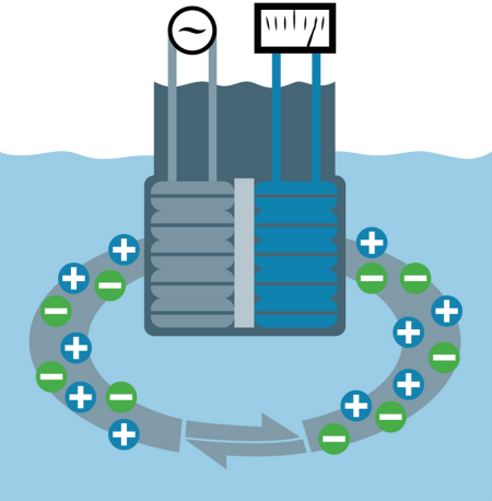
Fig. 2: Inductive sensor.
For processes with normal operating conductivity greater than 100 microSiemens/cm (µS/cm), inductive sensors are generally the technology of choice. Inductive sensors interact with the inside surfaces of flow cells and other vessels and pipes when closer than two to three inches from these surfaces. This interaction causes an apparent decrease in conductivity in non-conductive vessels and an increase in conductivity in conductive vessels. For this reason, calibration adjustments are most commonly done via the grab sample method.
Four-Pole: Also known as four- and six-electrode sensors. In four-pole sensors (figure 3) a current is applied across the outer electrodes. The analyzer continuously controls the current as required to maintain a constant voltage drop across the inner electrodes. As the current flow is increased, polarization of the outer electrodes occurs (Figure 3 right) but because the current flow is relatively low, there is little to no polarization of the inner electrodes throughout a broad conductivity operating range. The current applied to maintain a constant voltage potential between the inner electrodes is proportional to the conductivity of the solution.
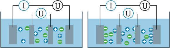
Fig. 3: Four-pole sensor.
The four-electrode sensor is popular in biotechnology applications such as chromatography since the sensor can operate across a wide conductivity range and operates well in very small volume flow cells with minimal influence from the inside walls of the vessel.
Next page
Conductivity Sensor Installation, Calibration, And Maintenance
All conductivity sensors must be installed with the sensor completely immersed and oriented to minimize the trapping of air bubbles. Most inductive sensors require at least one to two inches between the sensor and the inside surfaces of the pipe, flow cell, tank, process connections, etc.
Contacting and four-pole sensors can be calibrated using traceable standard solutions, but care must be taken to calibrate using conductivity values read from the temperature/conductivity table. Inductive sensors are generally calibrated to match a grab sample to offset the interferences from inside process surfaces in close proximity to the sensor.
For ultra-high purity water, calibration (cell constant) adjustments are made using standard solutions of greater than 74 µS/cm due to the impact of CO2 dissolving and increasing the conductivity of the standards. Specialized test equipment for comparative adjustment is helpful in some instances.
Process conditions, installation, sensor type, performance and validation requirements will all impact the frequency of maintenance and calibration. Generally, two-electrode sensors are installed in clean applications and will not require routine cleaning. Four-pole and inductive sensors in highly aggressive and fouling media should be inspected and cleaned as experience dictates.
pH Measurements
A pH sensor measures the activity of hydrogen ions in an aqueous solution and reflects the acidity or hydrogen ion concentration in dilute solutions. pH monitoring and control helps optimize production, insure quality and protect the environment in virtually any industry where water is used. Reliable pH sensors help protect people and the environment, and guarantee the quality of high-grade products across many, many industries and processes.
Three basic types of pH sensors are most commonly used:
Glass and pH Sensitive Enamel: These potentiometric measurements are based on a pH-sensitive membrane on which hydrogen ions accumulate, thereby causing electrical potential to build up (figure 4). The electrical potential and temperature are used to calculate the pH value according to the Nernst equation. The reference junction and liquid junction are chosen to provide a stable pH reference. The conductivity, temperature and other process properties must be considered when selecting the right reference and pH membrane for a given application.

Fig. 4: Glass or pH sensitive enamel pH sensor.
Next page
ISFET: The ISFET pH sensors (figure 5) have a field effect transistor (FET), which uses a specially coated gate. Hydrogen ions accumulate on this coating creating a higher voltage potential on the gate, resulting in an increase in the current flow through the transistor. The current flow and temperature are used to calculate the pH value according to the Nernst equation. The reference electrode and liquid junction are equally important in ISFET pH sensors as they are membrane based sensors.
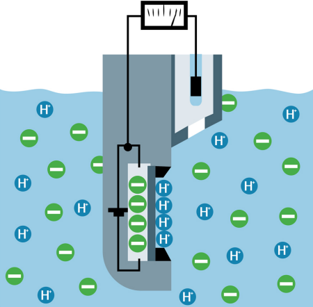
Fig. 5: ISFET pH sensor.
pH Sensor Installation, Calibration, And Maintenance
pH sensors and associated accessories must be properly applied, fully submersed and installed as recommended by your supplier. Most sensors need to be mounted such that the cable end of the sensor is at least 15 degrees above the measuring end to eliminate air bubbles inside the tip of the sensor (figure 6).
Fig. 6: pH sensors are mounted at an angle of at least 15 degrees to eliminate air bubbles. Here are various types of installation hardware.
There are many sensor types available, so be certain to use the sensor most compatible with your process conditions and performance requirements. Check that the installation hardware and location allow for the safe removal of the sensor for cleaning, calibration and replacement. Prior to a pH calibration, make sure to clean and rinse the sensor thoroughly, and follow supplier guidance for proper cleaning techniques for your pH sensor.
New sensors, and sensors that have been out of the process for extended periods of time, should be soaked in a pH 4 buffer solution or tap water for at least 30 minutes prior to calibration. For most applications, sensors should be calibrated in pH4 and pH7 buffer solutions for best results.
The actual interval between cleanings, calibration and final sensor failure is a function of the actual process/ambient conditions, installation, sensor configuration, cleaning and calibration technique, and sensor handling. Only experience with a specific pH sensor in a particular process will determine actual results. Slow response to changes, low slope and significant zero point shifts are all indications that the sensor is in need of cleaning, calibration and/or replacement.
Inductively-coupled digital sensor technology such as Memosens technology (an open industrial protocol) makes it possible to perform sensor calibration and troubleshooting in the lab or workshop to maximize process measurement availability by minimizing field maintenance activities. Clean, calibrated sensors are simply rotated into the process on a schedule or as necessary.
Next page
Turbidity/Total Suspended Solids
Turbidity sensors measure the amount light scattered as a result of particles or suspended solids in a solution. In drinking water, the turbidity value is an important measure of quality. In wastewater treatment, turbidity systems measure turbidity and use a multi-point calibration curve to calculate TSS (total suspended solids) from the turbidity value to control and monitor wastewater treatment processes for primary sludge, return activated sludge (RAS), waste activated sludge (WAS), sludge dewatering, aeration basin and outlet.
In a turbidity sensor, a beam of light (figure 7) is directed through the medium and scattered by suspended particles with a greater optical density. For the TSS measurement, the scattered light is correlated to the concentration of suspended solids in the process. "Backscatter" sensors extend the high end of the range considerably. Some sensors employ both nephelometric (90 degree) and backscatter (105 to 135 degrees) detectors in the same sensor, making it possible to measure very low to very high turbidity and corresponding TSS concentrations with the same sensor.

Fig. 7: Turbidity sensor.
Turbidity/TSS Sensor Installation, Calibration, And Maintenance
Turbidity/TSS sensor installations can vary greatly from application to application. In all turbidity applications, the sensor must be fully immersed in water and kept free from fouling and the buildup of bubbles or micro bubbles. Reflections and ambient light must also be eliminated, or effective compensation must be employed. The sensor must be accessible for inspection, cleaning and routine calibration checks and adjustments.
Whenever practical, the sensor should be installed directly in the process. In-situ installation avoids the problems associated with slip-stream installation such as the natural outgassing of dissolved gases as solution temperature increases and pressure drops. Debubbling accessories can have a direct impact on measurement reliability and error as well as decrease the frequencies of maintenance required.
The interval between cleanings and calibration checks/adjustments can be extended by proper installation, and by implementation of accessories such as ultrasonic and other field proven cleaning systems.
Turbidity calibrations are usually accomplished using a traceable liquid standard solution in combination with appropriate calibration accessories obtained from the supplier. TSS sensors should be calibrated using actual analyzed process samples to achieve the highest accuracy. Users must follow supplier calibration guidance and instructions to achieve the best results in TSS and turbidity applications. Because the size, shape, color and concentration of the TSS can impact the correlation between turbidity and TSS, multi-point calibration curves developed using various dilutions of a specific process may be employed as necessary to obtain a satisfactory correlation.
Solid-state liquid-free calibration reference check accessories can reduce the time and expense of using and disposing of toxic liquid turbidity standard solutions such as formazine. In many applications where high accuracy is not necessary, solid-state reference checks can eliminate the need for liquid calibrations altogether.
Depending on the application, cleaning and calibration checks/adjustments will be required periodically. In low turbidity applications where debubbling systems are used, cleaning of the debubbling chambers to remove built-up solids and silt will be necessary.
Next page
Dissolved Oxygen Sensors
As the name implies, dissolved oxygen (DO) sensors measure the amount of oxygen dissolved in a solution. This measurement can be used for controlling the aeration of activated sludge basins in wastewater treatment, residual oxygen measurement in power station boiler feed water and beverage bottling, fermentation in food processing, assessing color and taste in the production of red wine, and other processes.
Dissolved oxygen is a key water quality indicator when monitoring surface water or in water treatment systems such as boiler feedwater. It is also a critical factor in ensuring a highly effective aeration basin system, and in guaranteeing optimum conditions for fish farming.
Two types of DO sensors are commonly used:
Optical Sensors: In optical DO sensors (also known as fluorescence or luminescence sensors), marker molecules are excited by an internally generated, pulsed green or blue LED light and respond with pulsed red fluorescent light (figure 8). When no oxygen is present, the responding red pulse is strong and the recovery time is longest. When oxygen molecules are present, they reduce the fluorescent light through a process called "fluorescence quenching," resulting in a weaker pulse and faster recovery. The size of the pulse and the recovery time are both indicative of relative oxygen concentration.
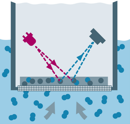
Fig. 8: Optical DO sensor.
In most wastewater applications, optical DO sensors are preferred because the sensors generally require less attention than amperometric DO sensors. Trace optical DO sensors for boiler feedwater and other applications are becoming more popular as optical DO technology matures.
Amperometric DO Sensor: Here, oxygen permeates a membrane and is reduced at the working electrode (cathode), creating an electric current in direct proportion to DO concentration (figure 9). Amperometric sensors will not function properly without sufficient flow past the sensor because the sensor actually consumes a small amount of oxygen from the process. It is important to note that even a small amount of fouling on the sensor can impede the permeation of oxygen through the membrane causing relatively large errors in the measurement.
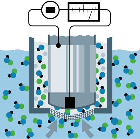
Fig. 9: Amperometric Sensor.
Amperometric DO sensors are more responsive and more accurate than optical DO sensors for trace applications, when properly maintained.
DO Sensor Installation, Calibration, And Maintenance
All DO sensors should be installed where there is sufficient flow past the sensor to remove bubbles from the surface of the sensor, impede fouling and to ensure a representative sample. Amperometric sensors have a minimum required flow velocity to maintain an accurate measurement. Most sensors will require maintenance, cleaning and replacement—and as such should be installed using accessories providing safe and easy access to the sensor. Automated air cleaning systems may be used to extend the cleaning interval in dirty applications such as wastewater aeration.
In trace applications such as boiler feed water, the flow, temperature and pressure must be stable and constant, and all tubing and fittings should be metallic to avoid permeation of oxygen into the sample stream.
Dissolved oxygen sensors are normally calibrated in ambient air with 100% relative humidity at known and stable temperature and pressure. In some cases, zero calibrations are performed using an inert gas such as nitrogen or an oxygen scavenger such as sodium bisulfite (NaHSO3) mixed in water.
In fermentation applications, the sensor is calibrated in the reactor vessel when partially full of fully oxygenated water at a constant and known pressure and temperature.
Calibration to a reference meter or lab titration is possible, but generally not recommended due to the high likelihood of calibration errors. Reference checks are helpful to determine whether or not the process sensor is trending with the process, but are not recommended for calibration adjustments.
Amperometric sensors require fresh electrolyte and new membrane caps periodically (typically, once or twice per year). Optical sensor luminescent caps must be replaced periodically (typically, once every two years). Supplier guidance should be followed, and caution used when cleaning an amperometric sensor as the membrane is often very delicate. Optical sensors are a bit more robust and can be wiped with a soft damp or wet cloth periodically; again, supplier guidance should be followed.
Amperometric sensors must be polarized prior to operation. After replacing the electrolyte or after the sensor has been disconnected for a period of time, the sensor must be polarized per supplier instructions by connecting the sensor to its powered transmitter. This polarization period can vary from thirty minutes to six hours or more depending on the sensor construction and application. Trace sensor can take considerably longer than six hours to polarize fully.
Next page
Chlorine Sensors
The measurement of chlorine and chlorine dioxide is needed in all areas of disinfection to ensure safe and effective water treatment. An amperometric free chlorine sensor normally has two electrodes—silver and gold— and an electrolyte buffer solution. The electrolyte allows only hypochlorous acid to reach the sensor. Chlorine is reduced at the gold electrode. The electron acceptance is proportional to the concentration of chlorine (hypochlorous acid) in solution.
As the pH of the process increases, the amount of hypochlorous acid decreases causing a decrease in the raw signal from the sensor. To report the total amount of "free" or "residual free" chlorine (hypochlorous acid plus hypochlorite ion), a pH compensation sensor is necessary.
Total chlorine sensors use different electrolyte solutions creating a system or sensor that is sensitive to both combined and free chlorine. In total chlorine sensors, pH compensation is not normally required and in some cases a reagent such as vinegar is required.
Chlorine Sensor Installation, Calibration, And Maintenance
Amperometric chlorine sensors should be installed where there is sufficient flow to meet the flow velocity specification for the sensor (generally, 0.5 to 1.0 linear feet per second). Free chlorine measurements are highly dependent on flow, pressure and pH. Special flow cells (figure 10) are used to maintain a stable and constant flow and pressure for the chlorine sensor. A pH sensor is used for compensation of the chlorine free measurement.

Fig. 10: Flow cell for amperometric chlorine sensor.
Chlorine sensors are calibrated to agree with a grab sample that is analyzed using a DPD (N,N-diethyl-p-phenylenediamine) test kit. Because the chlorine sensor requires a stable sample flow and pressure and because of the volatile nature of chlorine, it is not practical to calibrate using a standard solution.
Amperometric sensors must be calibrated when the process chlorine concentration and pH are stable and adequate to obtain a valid slope. For instance, it is not valid to perform a slope calibration when the chlorine concentration in the process is below supplier specified limits for the sensor. Calibrating outside of the supplier specified limits for pH or chlorine concentration for a sensor can cause erratic and unpredictable measurement results.
Summary
In all cases, sensors designed for continuous process operation are rugged, proven and sometimes use methods that are accepted by various government organizations, such as the EPA.
Calibration and maintenance procedures must be followed to keep the sensors operating properly and within reasonable tolerances. It is critical that sensors are properly applied and installed with appropriate hardware to allow simple and safe access to the sensor for routine maintenance and sensor replacement. Following vendor application, installation and maintenance guidelines will insure the sensor performs as reliably and predictably as practical.
About the Author
Jay Mershon has been consulting on process liquid and gas analyzers and systems since 1989. He joined Endress+Hauser in 2005, where he began his role as Senior Business Manager for Liquid Analytical products for the Eastern United States. Prior to joining Endress+Hauser, Jay served in various service, sales and sales management roles for more than 16 years at Emerson Process Management in support of the liquid and gas analysis business. Jay has authored and co-authored papers and articles on sensors and instrumentation for chemical and wastewater processes. He is a frequent speaker at State Water Environmental Association (WEA), State American Water Works Association (AWWA), State Rural Water Association, Local Sections of the International Society of Automation (ISA) events and other technical sessions.
Jay Mershon can be reached at (610) 906-1502 and [email protected].
Related Stories
Measuring Oxygen Purity with a Micro-Fuel Cell Sensor
Planning and Designing Gas Detection Systems
On-Site Trace Chemical Detection, Part 2: IMS and DMS Working Together