
Obtaining data from a sensor that is less than linear is easy enough if you need only a small portion of the sensor's output range. With this scenario, you can implement a simple, piecewise, linearization algorithm in your controller or processor. If you want a wider output range from the sensor, you can use analog linearization circuits to help tame that output. For instance, a resistor in series or parallel with a (nonlinear) thermistor will linearize a portion of the output, usually ±25°C (10-bit accurate) around a center point you have designed into the circuit. You can tune the center point of a thermistor response with the value of the added resistor. These circuit techniques can usually help you capture a wider but not total range of the sensor output. Hardware linearization techniques can be effective enough to serve most applications, but if the range limitations still affect the usefulness of your system, you can infuse flexibility into your circuit by using the programmability features of a microcontroller and a programmable gain amplifier (PGA).
 |
The Nonlinear Thermistor
The word thermistor originated from the descriptor thermally sensitive resistor. There are two basic types: negative temperature coefficient (NTC) and positive temperature coefficient (PTC). NTC thermistors are best suited for precision temperature measurements; PTCs, for switching applications. In this article we will focus on NTCs. Their applications range from devices that monitor and control automotive exhaust emissions, ice detectors, skin sensors, blood and urine analyzers, refrigerators, freezers, mobile phones, and battery pack chargers. They are also components of precision instrumentation such as handheld meters and temperature gauges.
NTC thermistors have three modes of operation. One is based on the thermistor's resistance vs. temperature characteristics. The other two take advantage of voltage vs. current and current over time. Applications using resistance vs. temperature are by far the most prevalent in industry. In contrast to applications using voltage vs. current and current over time, resistance vs. temperature circuits depend on a "zero-power" operating condition. Zero power implies that there is minimal self-heating of the thermistor. Figure 1 shows the resistance vs. temperature response of a 10 kΩ NTC thermistor. The 25°C rating for individual thermistors is typically 1 kΩ to 10 MΩ.
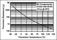 Figure 1. For precision temperature measurement applications, the thermistor is used in a "zero power" state that keeps the current through the thermistor low and thus greatly reduces self-heating effects on the element's resistance. The negative temperature coefficient 10 kΩ thermistor whose performance is graphed here is from Vishay/BCcomponents. |
Since the thermistor is a resistive element, current excitation is required. You can apply the current with a voltage or current reference. The performance of the thermistor in Figure 1 is reasonably repeatable as long as you keep the power across the device below the power dissipation capability of the package. Once you violate this thermal condition the thermistor will self-heat and artificially decrease in resistance, giving a higher-than-actual temperature reading.
In Figure 1, you can see the high degree of thermistor nonlinearity over temperature. You can correct the problem with a look-up table in your microcontroller but you will still need a high-resolution converter. Alternatively, you can apply hardware linearization techniques prior to digitization. One effective approach is to place a resistor in series with the thermistor and power supply. Figure 2 illustrates a seemingly obvious way to excite the thermistor and measure the change in resistance where the sensing element is excited with a current source.
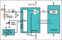 Figure 2. RA in series with VDD linearizes the thermistors temperature response. The external, low-pass filter eliminates aliasing problems. Microchips programmable gain amplifier (PGA) MCP6S26 sends the signal from the input, CH0, to the output of the device. The signal then changes to digital, using Microchips PIC16F684 internal 10-bit ADC. This circuit includes other optional sensors, such as a photosensor (CH1) or silicon temperature detector (CH2) at the multiplexed inputs of the PGA (CH1, CH2, CH3, CH4, and CH5). |
With this style of excitation, the thermistor current is low enough that the thermistor's dissipation constant remains below system accuracy requirements. If Microchip's MCP6S26 PGA is set at a gain of 1 V/V or replaced by a buffer amplifier, the circuit can effectively sense a limited temperature range (approximately ±25°C). The temperature range is not restricted by the amplifier, but rather by the linearity of the voltage divider built using the thermistor|RA combination. Temperature measurements over larger ranges have voltage deltas that are too small to accurately convert into a digital word unless you use a higher resolution ADC.
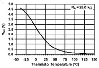 Figure 3. This is the response of the thermistor|RA combination illustrated in Figure 2. The thermistor circuit has good linear response in a ±25°C range surrounding the temperature where both resistors (NTC and RA) are equal. The error in this range is typically within ±1%. |
As an example, the temperature range of a typical thermistor from BCcomponents (www.vishay.com) is –40°C to 125°C. You will note in Figure 3 that the differential resistance for a 10°C delta at high temperatures is significantly larger than a 10°C delta at low temperatures. This diversity in the ratio of resistance to temperature over the range of this thermistor circuit creates an awkward analog problem. It is obvious here that a 10-bit ADC is inefficient over the full temperature range. Alternatives, such as increasing the resolution of the ADC or switching several resistors (RA) into the circuit, add cost and complexity. Another tack is to keep the components as they are in Figure 2 and take advantage of the PGA's capabilities.
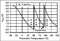 Figure 4. Signals from the Microchip microcontroller SPI port to the MCP6S26 PGA change the gain of this amplifier. The programmable gains of the PGA are +1, +2, +4, +5, +8, +10, +16, and +32 V/V. This application uses gains of 1, 8, and 32 V/V from the PGA to effectively cover the entire temperature range of the thermistor. The microcontroller introduces hysteresis to ensure that the calculated temperature values stay stable and immune to circuit noise. |
If you closely inspect the thermal response in Figure 3, you will note that granularity is lost at high temperatures. If you increase the PGA's gain at these higher temperatures, you will bring the PGA's output signal back into a range where the ADC can reliably identify temperatures (see Figure 4). Rather than hardware, this approach uses changes in the microcontroller code. Consequently, these adjustments to the circuit are almost free (minus the programmer's time). Figure 5 is a flow chart for the algorithm.
 Figure 5. This flow chart allows the microcontroller to calibrate the PGA to the proper gain setting. If the gain is too high or low, the microcontroller loops back until the PGA results match the appropriate setting for PGA gain vs. ADC output value. After it is verified that the ADC/PGA combination is appropriate, this value is linearized with a look-up table. |
The Microchip PIC16F684 firmware performs a real-time sample, reading the ADC value and passing it to the PGA's hysteresis routine, which checks the PGA gain setting. Based on PGA gain, the microcontroller tests for trip points (per Figure 4) with the ADC value. If this value is beyond a trip point, the microcontroller sets the PGA gain to the next higher or lower setting. Upon exiting the PGA hysteresis routine, the firmware checks whether the gain was changed. No change, and the program continues; if a change has occurred, the firmware rereads the ADC value.
Once the PGA gain and ADC values are known, they are passed to the piecewise linear interpolation (PwLI) routine. The microcontroller references the correct look-up table, per the PGA gain setting. The PwLI routine converts the 10-bit ADC value into a 16-bit fixed decimal point degrees Celsius value, a format that reports in tenths of a degree and thus provides better resolution (see Figure 6). In the final design, the designer can elect to report in tenths of a degree or round up in whole degrees.
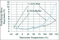 Figure 6. There are two plots in this figure. Plot #1 illustrates the total design error magnitude vs. thermistor temperature with the PGA in Figure 2 in the circuit. Plot #2 illustrates the total design error magnitude vs. thermistor temperature with a buffer amplifier replacing the PGA in Figure 2. Data from plot #2 assume the following errors: thermistor resistance error = 1%, ADC DC error ≤± 3.5 LSB, PGA gain error ≤± 0.1%, and PGA input offset error ≤± 1 mV. |
Summary
Getting data from a nonlinear sensor has always been a design challenge. The combination of a microcontroller and a PGA overcomes the nonlinearity of a thermistor across an extended temperature range. Not only does this technique work well with thermistors, but it is also handy for any sensor afflicted with nonlinear behavior characteristics.
For Further Reading
"2322 640 5... , NTC thermistors, accuracy line," Product Data Sheet, BCcomponents, September 27, 2001.
Baker, Bonnie C., "Thermistors in Single-Supply Temperature Sensing Circuits," AN685, Microchip Technology Inc., DS00685, 1999.
— — —, "Temperature Sensing with a Programmable Gain Amplifier," AN867, Microchip Technology Inc., DS00867, 2003.
Blake, Kumen, and Steven Bible, "Thermistor Temperature Sensing with MCP6SX2 PGAs," AN897, Microchip Technology Inc., DS00897, 2004.
Day, John, and Steven Bible, "Piecewise Linear Interpolation on PIC12/14/16 Series Microcontrollers," AN942, Microchip Technology Inc., 2004.
"Introduction to NTCs: NTC thermistors," Data Sheet, BCcomponents, March 27, 2001.
Bonnie C. Baker is Staff Architect Engineer, Microchip Technology Inc., Chandler, AZ; 480-792-7490, [email protected], www.microchip.com.