
Acoustic wave devices have been in commercial use for more than 60 years. The telecommunications industry is the largest consumer, accounting for ~3 billion acoustic wave filters annually, primarily in mobile cell phones and base stations. These are typically surface acoustic wave (SAW) devices, and act as bandpass filters in both the radio frequency and intermediate frequency sections of the transceiver electronics. Several of the emerging applications for acoustic wave devices as sensors may eventually equal the demand of the telecommunications market. These include automotive applications (torque and tire pressure sensors), medical applications (chemical sensors), and industrial and commercial applications (vapor, humidity, temperature, and mass sensors). Acoustic wave sensors are competitively priced, inherently rugged, very sensitive, and intrinsically reliable. Some are also capable of being passively and wirelessly interrogated (no sensor power source required).
Acoustic Wave Technology Overview
Acoustic wave sensors are so named because their detection mechanism is a mechanical, or acoustic, wave. As the acoustic wave propagates through or on the surface of the material, any changes to the characteristics of the propagation path affect the velocity and/or amplitude of the wave. Changes in velocity can be monitored by measuring the frequency or phase characteristics of the sensor and can then be correlated to the corresponding physical quantity being measured.
Virtually all acoustic wave devices and sensors use a piezoelectric material to generate the acoustic wave. Piezoelectricity was discovered by brothers Pierre and Paul-Jacques Curie in 1880, received its name in 1881 from Wilhelm Hankel, and remained largely a curiosity until 1921, when Walter Cady discovered the quartz resonator for stabilizing electronic oscillators [1]. Piezoelectricity refers to the production of electrical charges by the imposition of mechanical stress. The phenomenon is reciprocal. Applying an appropriate electrical field to a piezoelectric material creates a mechanical stress. Piezoelectric acoustic wave sensors apply an oscillating electric field to create a mechanical wave, which propagates through the substrate and is then converted back to an electric field for measurement.
Piezoelectric Substrate Materials
Figure 1. Acoustic wave devices are manufactured by means of a photolithographic process similar to that used to make ICs. The only difference is that no junction exists in acoustic wave sensors.
Among the piezoelectic substrate materials that can be used for acoustic wave sensors and devices, the most common are quartz (SiO2), lithium tantalate (LiTaO3), and, to a lesser degree, lithium niobate (LiNbO3). Each has specific advantages and disadvantages, which include cost, temperature dependence, attenuation, and propagation velocity. Table 1 lists some relevant specifications for each material, including the most popular cuts and orientations [2]. An interesting property of quartz is that it is possible to select the temperature dependence of the material by the cut angle and the wave propagation direction. With proper selection, the first order temperature effect can be minimized. An acoustic wave temperature sensor may be designed by maximizing this effect. This is not true of lithium niobate or lithium tantalate, where a linear temperature dependence always exists for all material cuts and propagation directions. Other materials with commercial potential include gallium arsenide (GaAs), silicon carbide (SiC), langasite (LGS), zinc oxide (ZnO), aluminum nitride (AlN), lead zirconium titanate (PZT), and polyvinylidene fluoride (PVdF).
Fabrication of Acoustic Wave Devices
Figure 2. A typical acoustic wave device consists of two sets of interdigital transducers. One transducer converts electric field energy into mechanical wave energy; the other converts the mechanical energy back into an electric field.
The sensors are made by a photolithographic process (see Figure 1). Manufac turing begins by carefully polishing and cleaning the piezoelectric substrate. Metal, usually aluminum, is then deposited uniformly onto the substrate. The device is spin-coated with a photoresist and baked to harden it. It is then exposed to UV light through a mask with opaque areas corresponding to the areas to be metalized on the final device. The exposed areas undergo a chemical change that allows them to be removed with a developing solution. Finally, the remaining photoresist is removed. The pattern of metal remaining on the device is called an interdigital transducer, or IDT. By changing the length, width, position, and thickness of the IDT, the performance of the sensor can be maximized.
Acoustic Wave Propagation Modes
Acoustic wave devices are described by the mode of wave propagation through or on a piezoelectric substrate. Acoustic waves are distinguished primarily by their velocities and displacement directions; many combinations are possible, depending on the material and boundary conditions. The IDT of each sensor provides the electric field necessary to displace the substrate and thus form an acoustic wave. The wave propagates through the substrate, where it is converted back to an electric field at the IDT on the other side. Figure 2 shows the configuration of a typical acoustic wave device. Transverse, or shear, waves have particle displacements that are normal to the direction of wave propagation and which can be polarized so that the particle displacements are either parallel to or normal to the sensing surface. Shear horizontal wave motion signifies transverse displacements polarized parallel to the sensing surface; shear vertical motion indicates transverse displacements normal to the surface.
Figure 3. Although it is the oldest acoustic wave device, the thickness shear mode resonator is still used for measuring metal deposition rates.
A wave propagating through the substrate is called a bulk wave. The most commonly used bulk acoustic wave (BAW) devices are the thickness shear mode (TSM) resonator and the shear-horizontal acoustic plate mode (SH-APM) sensor.
If the wave propagates on the surface of the substrate, it is known as a surface wave. The most widely used surface wave devices are the surface acoustic wave sensor and the shear-horizontal surface acoustic wave (SH-SAW) sensor, also known as the surface transverse wave (STW) sensor.
All acoustic wave devices are sensors in that they are sensitive to perturbations of many different physical parameters. Any change in the characteristics of the path over which the acoustic wave propagates will result in a change in output. All the sensors will function in gaseous or vacuum environments, but only a subset of them will operate efficiently when they are in contact with liquids. The TSM, SH-APM, and SH-SAW all generate waves that propagate primarily in the shear horizontal motion. The shear horizontal wave does not radiate appreciable energy into liquids, allowing liquid operation without excessive damping. Conversely, the SAW sensor has a substantial surface-normal displacement that radiates compression waves into the liquid, thus causing excessive damping. An exception to this rule occurs for devices using waves that propagate at a velocity lower than the sound velocity in the liquid. Regardless of the displacement components, such modes do not radiate coherently and are thus relatively undamped by liquids.
Other acoustic waves that are promising for sensors include the flexural plate wave (FPW), Love wave, surface-skimming bulk wave (SSBW), and Lamb wave. Before turning to application examples, it is helpful to briefly review each sensor type.
Figure 4. In the shear-horizontal acoustic plate mode (SH-APM) sensor, the waves travel between the top and bottom surfaces of the plate, allowing sensing on either side.
Bulk Wave Sensors
Thickness Shear Mode Resonator. The TSM, widely referred to as a quartz crystal microbalance (QCM), is the best-known, oldest, and simplest acoustic wave device. As shown in Figure 3, the TSM typically consists of a thin disk of AT-cut quartz with parallel circular electrodes patterned on both sides. The application of a voltage between these electrodes results in a shear deformation of the crystal.
This device is known as a resonator because the crystal resonates as electromechanical standing waves are created. The displacement is maximized at the crystal faces, making the device sensitive to surface interactions. The TSM resonator was originally used to meas ure metal deposition rates in vacuum systems where it was commonly used in an oscillator circuit [3]. The oscillation frequency tracks the crystal resonance and indicates mass accumulation on the device surface. In the late 1960s, the TSM resonator was shown to operate as a vapor sensor.
The TSM features simplicity of manufacture, ability to withstand harsh environments, temperature stability, and good sensitivity to additional mass deposited on the crystal surface [4]. Because of its shear wave propagation component, the TSM resonator is also capable of detecting and measuring liquids, making it a good candidate for a biosensor. Unfortunately, these devices have the lowest mass sensitivity of the sensors examined here. Typical TSM resonators operate between 5 and 30 MHz. Making very thin devices that operate at higher frequencies can increase the mass sensitivity, but thinning the sensors beyond the normal range results in fragile devices that are difficult to manufacture and handle. Recent work has been done to form high-frequency TSM resonators using piezoelectric films and bulk silicon micromachining techniques [5].
Figure 5. Rayleigh waves move vertically in a direction normal to the surface plane of a surface acoustic wave (SAW) sensor. SAW waves are very sensitive to surface changes, but do not work well for most liquid sensing applications.
Shear-Horizontal Acoustic Plate Mode Sensors. These devices use a thin piezoelectric substrate, or plate, functioning as an acoustic waveguide that confines the energy between the upper and lower surfaces of the plate (see Figure 4). As a result, both surfaces undergo displacement, so detection can occur on either side. This is an important advantage, as one side contains the interdigital transducers that must be isolated from conducting fluids or gases, while the other side can be used as the sensor.
As with the TSM resonator, the relative absence of a surface-normal component of wave displacement allows the sensor to come into contact with liquid for biosensor applications. SH-APM sensors have been successfully used to detect microgram-per-liter levels of mercury, which is adequate for Safe Drinking Water Act compliance testing [6]. Although more sensitive to mass loading than the TSM resonator, SH-APM sensors are less sensitive than surface wave sensors. There are two reasons: The first is that the sensitivity to mass loading and other perturbations depends on the thickness of the substrate, with sensitivity increasing as the device is thinned. The minimum thickness is constrained by manufacturing processes. Second, the energy of the wave is not maximized at the surface, which reduces sensitivity.
Surface Wave Sensors
Figure 6. The wave energy is confined to within one wavelength from the surface of a SAW sensor. This characteristic yields a sensor that is very sensitive to interactions with the surface.
Surface Acoustic Wave Sensors. In 1887, Lord Rayleigh discovered the surface acoustic wave mode of propagation [7] and in his classic paper predicted the properties of these waves. Named for their discoverer, Rayleigh waves have a longitudinal and a vertical shear component that can couple with a medium in contact with the devices surface (see Figure 5,71). Such coupling strongly affects the amplitude and velocity of the wave. This feature enables SAW sensors to directly sense mass and mechanical properties. The surface motion also allows the devices to be used as microactuators. The wave has a velocity that is ~5 orders of magnitude less than the corresponding electromagnetic wave, making Rayleigh surface waves among the slowest to propagate in solids. The wave amplitudes are typically ~10 Å and the wavelengths range from 1 to 100 microns [8].
Figure 6 details the deformation field caused by a SAW propagating along the Z-axis and the associated distribution of potential energy. Because Rayleigh waves have virtually all their acoustic energy confined within one wavelength of the surface, SAW sensors have the highest sensitivity of the acoustic sensors reviewed.
Typical SAW sensors operate from 25 to 500 MHz. One disadvantage of these devices is that Rayleigh waves are surface-normal waves, making them poorly suited for liquid sensing. When a SAW sensor is contacted by a liquid, the resulting compressional waves cause an excessive attenuation of the surface wave.
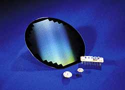
Photo 1. Acoustic wave sensors are commercially available in several form factors. Most sensors begin as processed wafers that are then tested, diced, and mounted into packages.
Shear-Horizontal Surface Acoustic Wave Sensors. If the cut of the piezoelectric crystal material is rotated appropriately, the wave propagation mode changes from a vertical shear SAW sensor to a shear-horizontal SAW sensor. This dramatically reduces loss when liquids come into contact with the propagating medium, allowing the SH-SAW sensor to operate as a biosensor (see Figure 7).
Comparison of Acoustic Wave Sensors
In general, the sensitivity of the sensor is proportional to the amount of energy in the propagation path being perturbed. Bulk acoustic wave sensors typically disperse the energy from the surface through the bulk material to the other surface. This distribution of energy minimizes the energy density on the surface, which is where the sensing is done. SAW sensors, conversely, focus their energy on the surface, tending to make them more sensitive [9,10] (see Table 2). Other design considerations when selecting acoustic wave sensors include oscillator stability and noise level.
Sensor Applications
All acoustic wave sensors are sensitive, to varying degrees, to perturbations from many different physical parameters. Some commercially available acoustic wave sensors are shown in Photo 1. As a matter of fact, all acoustic wave devices manufactured for the telecommunications industry must be hermetically sealed to prevent any disturbances because they will be sensed by the device and cause an unwanted change in output.
Figure 7. By correctly selecting the orientation of material cut, shear-horizontal surface acoustic waves (SH-SAW) will dominate. These waves have a displacement that is parallel to the devices surface.
The range of phenomena that can be detected by acoustic wave devices can be greatly expanded by coating the devices with materials that undergo changes in their mass, elasticity, or conductivity upon exposure to some physical or chemical stimulus. These sensors become pressure, torque, shock, and force detectors under an applied stress that changes the dynamics of the propagating medium. They become mass, or gravimetric, sensors when particles are allowed to contact the propagation medium, changing the stress on it. They become vapor sensors when a coating is applied that absorbs only specific chemical vapors. These devices work by effectively measuring the mass of the absorbed vapor. If the coating absorbs specific biological chemicals in liquids, the detector becomes a biosensor. As previously noted, a wireless temperature sensor can be created by selecting the correct orientation of propagation. The propagating medium changes with temperature, affecting the output. Detailed below are some of the more common applications of acoustic wave sensors.
Temperature Sensor. Surface wave velocities are temperature dependent and are determined by the orientation and type of crystalline material used to fabricate the sensor. Temperature sensors based on SAW delay line oscillators have millidegree resolution, good linearity, and low hysteresis [11]. They are, however, very sensitive to mass loading and so must be sealed in a hermetic package. A 124 MHz ST-cut quartz, surface-skimming bulk wave temperature sensor was recently reported to have a temperature coefficient of 32 ppm/ÞC and a resolution of 0.22ÞC [12]. It also exhibited three orders of magnitude less sensitivity to mass loading than do SAW sensors. The response time was found to be 0.3 s, 10 3 faster than BAW sensors. These temperature sensors have the additional advantage of requiring no power and of being wireless, making them well suited for use in remote locations.
Pressure Sensor. In 1975, the first reported use of SAW technology for a sensor application was in the form of a pressure sensor [13]. SAW velocities are strongly affected by stresses applied to the piezoelectric substrate on which the wave is propagating. A SAW pressure sensor is therefore created by making the SAW device into a diaphragm (see Figure 8,).
Figure 8. The frequency of the SAW changes with stress. As the diaphragm flexes due to pressure, the SAW sensor changes its output. Unfortunately, changes in temperature also cause a change in output.
The uncompensated temperature drifts that tend to interfere with SAW pressure sensors can be minimized by placing a reference SAW device close to the measuring SAW on the same substrate and mixing the two signals [14]. One sensor acts as a temperature detector, whose proximity to the pressure sensor ensures that both are exposed to the same temperature. However, the temperature sensor SAW must be isolated from the stresses that the pressure SAW experiences (see Figure 9).
SAW pressure sensors are passive (no power required), wireless, low cost, rugged, and extremely small and lightweight, making them well suited for measuring pressure in moving objects (e.g., car and truck tires). These characteristics offer advantages over technologies such as capacitive and piezoresistive sensors, which require operating power and are not wireless. A SAW pressure sensor weighing <1 g, with a resolution of 0.73 psi, was recently integrated into a car tire with excellent results [15]. Such a system allows the operator to view the pressure in each tire from the comfort of the cabin. Correctly inflated tires lead to improved safety, greater fuel efficiency, and longer tire life. This technology is particularly interesting for the new run-flat (also called zero pressure or extended mobility) tire market.
Torque Sensor. If a SAW device is rigidly mounted to a flat spot on a shaft, and the shaft experiences a torque, this torque will stress the sensor and turn it into a wireless, passive, lightweight torque detector. As the shaft is rotated one way, the SAW torque sensor is placed in tension; rotated the other way, it is placed in compression. For practical applications, two SAW torque sensors are used such that their centerlines are at right angles (see Figure 10) [16]. Thus, when one sensor is in compression, the other is in tension. Since both sensors are exposed to the same temperature, the sum of the two signals minimizes any temperature drift effects.
Figure 9. Adding a second, strategically placed SAW effectively minimizes the temperature drift of the SAW pressure sensor.
In comparison to other torque sensors, including resistive strain gauges, optical transducers, and torsion bars, SAW torque sensors offer lower cost, higher reliability, and wireless operation. Monitoring torque on trucks and cars will significantly improve handling and braking because torque meas ures wheel traction much better than the rpm sensors in current use.
Mass Sensor. Of all the devices evaluated here, SAW sensors are the most sensitive to mass loads. This opens up several applications including particulate sensors and film thickness sensors. If the sensor is coated with an adhesive substance, it becomes a particulate sensor; any particle landing on the surface will remain there and perturb the wave propagation. A mass resolution of 3 pg for a 200 MHz ST-cut quartz SAW has been reported, which was 1000 3 the sensitivity of the 10 MHz TSM resonator tested [17]. Particulate sensors are used in cleanrooms, air quality monitors, and atmos pheric monitors.
Thickness sensors operate on basically the same principle as particulate sensors, except that they are not coated. The measured frequency shift is proportional to the mass of the deposited film, so the sensor provides thickness data by measuring the film density and acoustic impedance. This method is accurate, provided that the film is thin (ideally no more than a few percent of the acoustic wavelength) [18]. Most commercially available thickness sensors are based on TSM resonators. Although not so sensitive as SAW sensors, these devices offer ease of use and adequate sensitivity.
Dew Point/Humidity Sensor. If a SAW sensor is temperature controlled and exposed to the ambient atmosphere, water will condense on it at the dew point temperature, making it an effective dew point sensor. Current commercial instruments for high-precision dew point measurements are based on optical techniques, which have cost, contamination, accuracy, sensitivity, and long-term stability issues. A 50 MHz YZ-cut lithium niobate SAW dew point sensor has been developed that is immune to common contaminants, has a resolution of ±0.025°C (vs. ±0.2°C for an optical sensor), is low cost, and is significantly more stable [19].
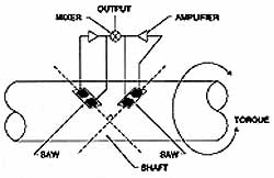
Figure 10. The stress in the shaft is transferred to the SAW sensor, which changes its output frequency with stress and, therefore, torque. The addition of another SAW minimizes temperature effects.
Acoustic wave sensors with an elastic hygroscopic polymer coating make excellent humidity detectors. Three operational mechanisms contribute to the sensors response: mass loading, acoustoelectric effects, and viscoelastic effects, each of which can be effectively controlled to yield an accurate, low-cost, humidity sensor. A 50 MHz YZ-cut lithium niobate SAW sensor coated with polyXIO has been demonstrated as a humidity sensor with a range of 0%100% RH and a hysteresis on the order of 5% [20]. In addition, a 767 MHz AT-cut quartz SH-SAW sensor coated with a plasma-modified hexamethyldisiloxane (HMDSO) has recently been demonstrated as a humidity sensor, with a sensitivity of 1.4 ppm/% RH and a 5% hysteresis. This was found to be 410 3 more sensitive than a 14 MHz TSM resonator coated with the same polymer [21].
In the same category, a 434 MHz YZ-cut lithium niobate SAW sensor has been used as a remote water sensor [22], and an 86 MHz XY-cut quartz Love wave sensor has been demonstrated as an ice sensor [23].
Vapor Chemical SensorCoated and Uncoated. Chemical vapor sensors based on SAW devices were first reported in 1979 [24]. Most of them rely on the mass sensitivity of the detector, in conjunction with a chemically selective coating that absorbs the vapors of interest and results in an increased mass loading of the device (see Figure 11). As with the temperature-compensated pressure sensors, one SAW is used as a reference, effectively minimizing the effects of temperature variations.
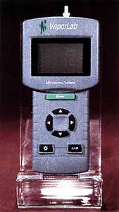
Photo 2. A commercially available handheld SAW chemical vapor analyzer incorporates an array of four SAW sensors, each coated with a different polymer.
Several design considerations must be satisfied when selecting and applying the chemically sorptive coating. Ideally, the coating is completely reversible, meaning that it will absorb and then completely desorb the vapor when purged with clean air. The rate at which the coating absorbs and desorbs should be fairly quick, <1 s, for instance. The coating should be robust enough to withstand corrosive vapors. It should be selective, absorbing only very specific vapors while rejecting others. The coating must operate over a realistic temperature range. It should be stable, reproducible, and sensitive. And finally, its thickness and uniformity are very important.
When several SAW sensors, each with a unique chemically specific coating, are configured as an array, each will have a different output when exposed to a given vapor. Pattern recognition software allows a diverse list of volatile organic compounds thus to be detected and identified, yielding a very powerful chemical analyzer. A commercially available analyzer with an array of four SAW sensors is shown in Photo 2.
TSM resonators have also successfully been used for chemical vapor sensing [25] but they are significantly less sensitive than their SAW counterparts. In addition, SAW chemical vapor sensors have been made without coatings. This method uses a gas chromatograph column to separate the chemical vapor components, and a temperature-controlled SAW that condenses the vapor and measures the corresponding mass loading [26].
Figure 11. By coating a SAW device with a chemically sorptive polymer, a chemical vapor sensor is made. Adding another SAW device minimizes the temperature drift and provides a manageable difference frequency.
Biosensor. Similar to chemical vapor sensors, biosensors detect chemicals, but in liquids rather than vapors. As noted earlier, the SAW device is a poor choice for this application, as the vertical component of the propagating wave will be suppressed by the liquid. Biosensors have been fabricated using the TSM resonator, SH-APM, and SH-SAW sensors. Of all the known acoustic sensors for liquid sensing, the Love wave sensor, a special class of the shear-horizontal SAW, has the highest sensitivity [27]. To make a Love wave sensor, a waveguide coating is placed on a SH-SAW device such that the energy of the shear horizontal waves is focused in that coating. A biorecognition coating is then placed on the waveguide coating, forming the complete biosensor. Successful detection of anti-goat IgG in the concentration range of 3 3 108106 moles using a 110 MHz YZ-cut SH-SAW with a polymer Love wave guide coating has been achieved [28].
Guide to Abbreviations
BAW
FPW
IDT
QCM
SAW
SH-APM
SH-SAW
SSBW
STW
TSMBulk acoustic wave
Flexural-plate wave
Interdigital trans-ducer
Quartz crystal- microbalance
Surface acoustic wave
Shear-horizontal acoustic plate mode
Shear-horizontal sur-face acoustic wave
Surface-skimming bulk wave
Surface transverse wave
Thickness shear mode
Conclusion
Acoustic wave sensors are extremely versatile devices that are just beginning to realize their commercial potential. They are competitively priced, inherently rugged, very sensitive, and intrinsically reliable, and can be interrogated passively and wirelessly. Wireless sensors are beneficial when monitoring parameters on moving objects, such as tire pressure on cars or torque on shafts. Sensors that require no operating power are highly desirable for remote monitoring of chemical vapors, moisture, and temperature. Other applications include measuring force, acceleration, shock, angular rate, viscosity, displacement, and flow, in addition to film characterization. The sensors also have an acoustoelectric sensitivity, allowing the detection of pH levels, ionic contaminants, and electric fields. Surface acoustic wave sensors have proved to be the most sensitive in general as a result of their larger energy density on the surface. For liquid sensing, a special class of shear-horizontal surface acoustic wave sensors called Love wave sensors proved to be the most sensitive. Much work is continuing in developing these sensors for future applications.
References
1. A. Ballato. 1996. Piezoelectricity: History and New Thrusts, Proc Ultrasonics Symposium, Vol. 1:575-583.
2. D. Morgan. 1991. Surface-Wave Devices for Signal Processing, Elsevier, Amsterdam:152.
3. H. Wohltjen et al. 1997. Acoustic Wave SensorTheory, Design, and Physico-Chemical Applications, Academic Press, San Diego:39.
4. M. Schweyer et al. 1997. A Novel Monolithic Piezoelectric Sensor, Proc Ultrasonics Symposium, Vol. 1:371-374.
5. S. Martin. 1996. Gas Sensing with Acoustic Devices, Proc Ultrasonics Symposium, Vol. 1:423-434.
6. M. Schweyer et al. 1996. An Acoustic Plate Mode Sensor for Aqueous Mercury, Proc Ultrasonics Symposium, Vol. 1:355-358.
7. J.W.S. Rayleigh. 1885. Proc London Math Soc, Vol. 17:4-11.
8. H. Wohltjen. 1987. Surface Acoustic Wave Microsensors, Transducers.
9. H. Wohltjen et al. 1997. op. cit.:144.
10. J. Grate, S. Martin, and R. White. 1993. Acoustic Wave Microsensors, Analytical Chemistry, Vol. 65, No. 21:940-948.
11. H. Wohltjen. 1987. op. cit.
12. C. Wold et al. 1991. Temperature Measure ment Using Surface Skimming Bulk Waves, Proc Ultrasonics Symposium, Vol. 1:441-444.
13. D. Cullen and T. Reeder. 1975. Measurement of SAW Velocity Versus Strain for YX and ST Quartz, Proc Ultrasonics Symposium:519-522.
14. D. Cullen and T. Montress. 1980. Progress in the Development of SAW Resonator Pressure Transducers, Proc Ultrasonics Symposium, Vol. 2:519-522.
15. A. Pohl et al. 1997. Monitoring the Tire Pressure of Cars Using Passive SAW Sensors, Proc Ultrasonics Symposium, Vol. 1:471-474.
16. U.S. Patent No. 5,585,571.
17. W. Bowers, R. Chuan, and T. Duong. 1991. A 200 MHz Surface Acoustic Wave Resonator Mass Microbalance, Re Sci Instrum, Vol. 62 (6):1624-1629.
18. J. Grate, S. Martin, and R. White. op. cit.
19. K. Vetelino et al. 1996. Improved Dew Point Measurements Based on a SAW Sensor, Sensors and Actuators, Vol. B 35-36:91-98.
20. J. Cheeke, N. Tashtoush, and N. Eddy. 1996. Surface Acoustic Wave Humidity Sensor Based on the Changes in the Viscoelastic Properties of a Polymer Film, Proc Ultrasonics Symposium, Vol. 1:449-452.
21. E. Radeva and I. Avramov. 1998. Humidity Sensing Properties of Plasma Polymer Coated Surface Transverse Wave Resonators, Proc Ultrasonics Symposium, Vol. 1:509-512.
22. L. Reindl et al. 1999. Passive Radio Requestable SAW Water Content Sensor, Proc Ultrasonics Symposium, Vol. 1:461-466.
23. M. Vellekoop and B. Jakoby, 1999. A Love-Wave Ice Detector, Proc Ultrasonics Symposium, Vol. 1:453-456.
24. H. Wohltjen and R. Dessy. 1979. Surface Acoustic Wave Probe for Chemical Analysis I. Introduction and Instrument Design, Ana Chem, Vol. 51 (9):1458-1475.
25. T. Nakamoto, K. Nakamura, and T. Moriizumi. 1996. Study of Oscillator-Circuit Behavior for QCM Gas Sensor, Proc Ultrasonics Symposium, Vol. 1:351-354.
26. E. Staples. 1999. Electronic Nose Simulation of Olfactory Response Containing 500 Orthogonal Sensors in 10 Seconds, Proc Ultrasonics Symposium, Vol. 1:417-423.
27. G. Kovacs. and M. Venema. 1992. Theoretical Comparison of Sensitivities of Acoustic Shear Wave Modes for Biochemical Sensing in Liquids, Appl Phys Lett, Vol. 61, No. 6:639.
28. E. Gizeli et al. 1997. Antibody Binding to a Functionalized Supported Lipid Layer: A Direct Acoustic Immunosensor, Anal Chem, Vol. 69:4808-4813.