

Summary
Pressure sensing, originating with atmospheric pressure (barometric pressure) sensing instruments in the 1600s, is important for medical, consumer, industrial, and aerospace applications. Microelectromechanical Systems (MEMS) pressure sensors have distinct advantages for pressure measurement applications as a result of their proven ruggedness, reliability, small form factor, and low cost.
Design engineers wanting to incorporate MEMS pressure sensors into new and existing products need to optimize a considerable number of sensor performance characteristics. Additionally, the chips must be sourced as best fits the commercial plans. The typical choices are off-the-shelf MEMS pressure sensors, custom sensors, or semi-custom sensors. Semi-custom MEMS pressure sensors offer the possibility to simultaneously reduce system costs, optimize system performance, and speed time-to-market.
Introduction
What are the important considerations when it comes to choosing off-the-shelf, custom, or semi-custom MEMS pressure sensors?
Off-the-shelf MEMS pressure sensors have the singular advantage of being readily available from a number of different qualified vendors, but come with a fixed combination of specifications that might result in performance compromises for a particular application. Choosing off-the-shelf components often makes sense when low unit cost is a priority, or when short time-to-market is required, or when the tolerances of the pressure sensor component are flexible in the overall system design specifications.
Fully custom MEMS pressure sensors can make sense when there is something unusual about the MEMS pressure sensor specification, when the sensors enable major competitive advantages for the product, or when there is a critical need to control the supply chain for quality control, regulatory, or barrier-to-entry reasons. However, fully custom devices can incur large investments in non-recurring engineering, as well as possibly requiring additional investment in new capital equipment and tooling. There are MEMS foundries around the world available to execute fully custom MEMS pressure sensor designs, however it will be years from design start to having production-qualified, fully custom MEMS pressure sensors available.
Semi-custom MEMS pressure sensors give flexibility to a broad class of users without the investment required for launching a fully custom MEMS pressure sensor product. The term semi-custom refers to strategic standardization of some aspects of the MEMS pressure sensor design and manufacturing process, for example those adopted in AMFitzgerald's RocketMEMS program. Strategic standardization results in an effective, adjustable solution for engineers wanting to quickly and efficiently integrate MEMS pressure sensors into new products for production volumes on the order of thousands to hundreds of thousands of units.
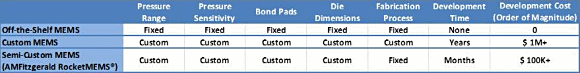 Table 1: Comparison of three sensor procurement options with respect to the major performance specifications common to MEMS pressure sensors.. (Click image for larger version) |
The advantages of the semi-custom approach for MEMS pressure sensor performance are optimization, system cost reduction, and design space freedom. These are considered at greater depth in the following three examples.
Example One: Sensor Performance Optimization using a Semi-Custom Approach
If we inspect the input/output sensor plot in Figure 1, we have the sensor input, i.e. pressure, on the x-axis and the sensor output, i.e. voltage, on the y-axis. The input/output lines for two MEMS sensors are represented here by the blue line (Sensor A) and the red line (Sensor B). Sensor A represents a typical MEMS pressure sensor.
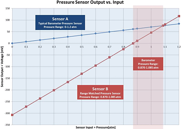
Fig. 1: Example input/output plot for two pressure sensors: a typical MEMS pressure sensor, Sensor A (blue line), and a range-matched semi-custom sensor, Sensor B (red line).
The input pressure range is 0-1.2 atm, and the output voltage range is 0-84 mV. The slope of the line corresponds to the sensor sensitivity, which is 70 mV/atm. The y-intercept, known as the offset, passes through zero volts. For an application that might experience a minimum pressure near zero and a maximum pressure of 1.2 atm, this is a well-suited sensor.
However, consider the common barometer. In the history of weather record keeping, the highest barometric pressure ever recorded is 1.085 atm, measured in 2001 in Mongolia. The lowest non-tornadic, i.e. non-transient, barometric pressure ever recorded is 0.870 atm, measured in 1979 in the eye of Super Typhoon Tip in the Pacific Ocean.
Even with these weather extremes, the majority of Sensor A's range would be unused. At 0.870 atm, Sensor A has an output voltage of about 61 mV and, at 1.085 atm, the sensor output is 76 mV. For the entire possible barometric pressure range, from the lowest historic weather extreme to the highest, Sensor A uses only 15 mV of the output range.
Yet despite this limited output range, if one were choosing a pressure sensor to purchase off-the-shelf, one would probably choose a sensor similar to Sensor A. In the pressure sensor market, while it is possible to select the upper end of the pressure range, the lower end is typically set to zero volts at zero pressure. This means the sensor's range between zero and the application's lowest pressure value will be unused.
What if it were possible to match both the lower and upper ends of the sensor range to the application range? Consider Sensor B, represented by the red line, in Figure 1. At the highest barometric pressure, the Sensors A and B have the same output voltage of 76 mV. However, instead of a zero offset, Sensor B has an offset, i.e. y-intercept, of -307 mV. This sets the sensor output of the lowest barometric pressure, 0.870 atm, to 0 mV.
One can see that with range matching, Sensor B has a steeper slope, which means it is a more sensitive sensor. The extremes of weather barometric pressure are now mapped from 0-76 mV output, instead of 61-76 mV, and accordingly, Sensor B exhibits 5x more sensitivity.
It is possible to electronically offset Sensor A's output by -61 mV and then amplify the signal, but this approach does not increase the resolution of the sensor. The sensor noise, as well as the signal, will be amplified. Only an increase in the sensitivity (the slope of the sensor input/output plot), or a reduction in sensor noise, will increase the resolution of the sensor.
Others may point out that the slope of the sensor is unrelated to the offset shift, and the slope may be increased independently of the offset. This is correct. However, when one considers the next stages of the signal chain, typically amplification and digital-to-analog conversion, the importance of offset and slope-matching to the application can be seen.
For example, consider a 5V system power supply. In this case, the maximum amplification for both sensors is 65x. The amplification factor is set by the highest voltage sensor output, 76 mV, which can be maximally amplified 65x, up to the supply voltage of 5V. At 65x, Sensor A's minimum output of 61 mV is amplified to 4V, whereas Sensor B's minimum output of 0 V remains 0 V. The result is that the post-amplification span of Sensor A is only 1 V, ranging from 4-5 V, while Sensor B utilizes the full supply voltage span from 0-5 V. These voltage ranges then become inputs to the digital-to-analog conversion (DAC) stage. Sensor B naturally fills the entire input range to the DAC, whereas Sensor A only fills a fraction of the DAC input range.
To employ this range-matching technique, the system designer must have the opportunity to tune both sensitivity and offset for the application. With AMFitzgerald's RocketMEMS semi-custom MEMS pressure sensors, as one example, the sensor's range can be matched to the application's range, and system performance can be improved without increasing sensor unit cost.
Example Two: System Cost Reduction through a Semi-Custom Approach
A sensor optimized for the system can reduce overall system costs, reduce system size, and increase system reliability. Take, for example, something as simple as bond pad location. Figure 2 illustrates two situations in which the system designer may have selected the ideal pressure sensor and the ideal ASIC, based on electrical performance considerations alone.
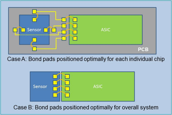
Fig. 2: System costs can be reduced, system size can be decreased, and system reliability can be improved by considering something as simple as chip bond pad location.
In Case A, the pressure sensor has a pad layout where its four bond pads are arranged optimally for the sensor's internal Wheatstone bridge configuration, i.e. north, south, east, and west. The ASIC, which may have been produced by a different manufacturer, has its bond pads arranged optimally for the ASIC's internal signal flow, i.e. near the analog input stage of the ASIC.
To connect the sensor and ASIC correctly, a third component, the PCB board, is needed to route the signals, and eight wirebonds are needed to connect the two chips to the PCB. The PCB is a significant additional cost to the system and is the largest component. Moreover, the overall reliability of the system is decreased, since wirebonds are a common point of failure in electronic systems.
In Case B, instead of each chips' bond pads being positioned optimally for its own internal structure, the chips' bond pads are positioned optimally for the overall system, i.e. the pressure sensor bond pads are placed to correspond to the ASIC bond pads. Arranged this way, the PCB routing layer can be eliminated, and fewer wirebonds are needed, thereby reducing system cost, decreasing overall system size, and increasing reliability.
When selecting pressure sensors, often overlooked device parameters, such as pad location, can make large differences in overall system cost, size, and reliability. However, there is no standard pad layout for signal processing ASICs, or for MEMS pressure sensors. As a result, most systems rely on a mix-and-match approach and apply the necessary workarounds, such as PCB boards, to interface these components.
A system such as RocketMEMS allows system designers to specify bond pad location, offset, sensitivity, and many other pressure sensor electrical and mechanical parameters. This flexibility enables system designers to optimize the sensor from the system-level perspective, which can increase reliability and performance, while simultaneously reducing system size and per-unit cost.
Example Three: The Combinatorial Search for the Perfect Sensor
The previous two examples illustrate how a few parameters, when optimized correctly, can benefit the overall system. Figure 3 illustrates some of the customizable parameters of a RocketMEMS pressure sensor. This is a partial list, but even with this list, one can see that the number of parameter combinations, and therefore the number of possible sensor designs, is high.
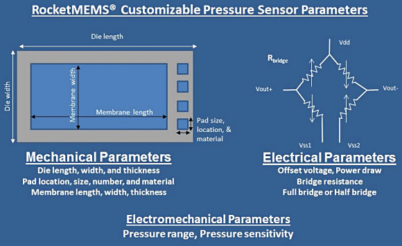
Fig. 3: Some of the customizable parameters of the RocketMEMS pressure sensor.
A typical sensor manufacturer must predict which sensor parameter combinations will be demanded and when. Traditionally, the manufacturer simplifies this difficult task by producing sensor designs optimized for only the most popular applications. In the case of MEMS pressure sensors, most sensor designs have been targeted for consumer electronics and automotive applications. Even then, as discussed in the first example, nearly all of these sensors have a zero offset, and cannot be range-matched to many applications.
For a system designer, there is a large parameter space that must be searched to find the sensor that is the best fit for the application. If the system designer's requirements fall largely parallel to popular applications, then the system designer may be in luck and a good enough pressure sensor may already be available for purchase. But if the system designer has a single unusual parameter requirement, it is unlikely that the optimal pressure sensor is available for purchase. Or perhaps, the system designer has identified several pressure sensor candidates, but none have the correct combination of sensitivity, offset, pad layout, etc. The system designer will then need to employ workarounds, which may reduce system performance, increase system costs, and decrease reliability, to work with the less-than-ideal sensor.
Alternatively, there is the semi-custom option. As one available option out there, AMFitzgerald offers semi-custom MEMS pressure sensors whose parameters may be optimized, as illustrated by the partial list in Figure 3. These chips are termed semi-custom because some aspects of the design have been standardized, while others may be customized. But even with some limits to the design space, semi-custom chips are able to address the needs of most applications. The benefits of the semi-custom approach are that chip development costs are decreased by an order of magnitude, and development times are reduced from years to months.
In the RocketMEMS program, the system designer dictates the sensor specifications. AMFitzgerald selects one of its reference sensor designs, tailors the design to specification, and has the chips fabricated. The system designer receives the chips several months later. Chip volumes may range from several hundred for prototyping to thousands or millions of devices for volume production.
Conclusion
MEMS pressure sensors are increasingly used for pressure measurement applications as a result of their proven ruggedness, reliability, small form factor, and low cost. Design engineers who would like to incorporate MEMS pressure sensors into new and existing products need to optimize a considerable number of performance specifications, and also need to choose among several sources, such as off-the-shelf MEMS pressure sensors, custom sensors, or semi-custom sensors, to best fit their business model and commercial plans. Semi-custom MEMS pressure sensors, as a result of standardization of some aspects of the MEMS pressure sensor design and manufacturing process, allow designers to quickly and efficiently specify and purchase MEMS pressure sensors optimized for their new products at considerable competitive advantage and at reasonable cost.
About the Authors
Dr. Charles C. Chung, PhD has over 18 years of engineering experience with MEMS devices. He has worked on multiple MEMS devices, including gyroscopes, microphones, pressure sensors, accelerometers, and DNA sequencing chips. He has also worked on MEMS projects at several companies, including Intel, General MEMS, LV Sensors, Atmel, and Halcyon Molecular, and AM Fitzgerald. Contact info: [email protected]
Paul Werbaneth is an independent consultant researching and analyzing technology and business topics in the microelectronics space. He is also a contributing editor and Technical Advisory Board member at 3D InCites. Contact info: [email protected]
Related Stories
Saturas Completes Successful Initial Field Trials of Embedded Stem Water Potential Sensor
SmartRounds Creates World's First Non-Lethal Non-Impact Smart Bullets
OmniVision and Wavelens Bring MEMS-Based High-Speed Autofocus to Next-Generation Smartphones
MEMSensing Launches Smallest Commercial 3-Axis Accelerometer MSA330 with SMIC