
Accurate and less intrusive measurement of real-time current draw is increasingly important for many electronic systems. Measurement of voltage drop in parasitic resistances or drain-source drop of driving FETs have been successfully used as an indirect way to calculate current draw in drive applications. But as requirements for precise measurement increase, such as in 15A to 35A rated lead-acid battery chargers, motor/actuator load to environment correlation, solar inverters, and system monitoring, how does an engineer address the challenge?
The Shunt
A shunt resistor has historically been the standard for accurate current measurement. Power dissipation, and thus heat, can however be very high when trying to achieve high-resolution. In addition, applied shunts also contribute to circuit impedance.
Ohm's law, V = I × R, states that Voltage (V) is the product of current (I) flowing through a resistance (R). By inserting a shunt resistor into a circuit, microcontrollers and/or FPGAs can measure that same current using an A/D port, OpAmp, and associated circuitry around the shunt.
Power (P) is released as heat and increases with the value of resistance (R). So while a larger (R) improves resolution, heat production is increased as well by P = I² × R. The power dissipation capabilities of the shunt must also be carefully considered, since accuracy can be compromised as the resistance of the shunt changes with heat. In fact, beyond 20A, the power dissipated by a shunt makes the solution impractical.
Finally, if Galvanic isolation is required, additional circuitry and optocouplers are necessary. Especially with currents higher than 20A, the desire then is to find a means to measure current that is less intrusive and without power loss or added circuit impedance.
Hall Effect Sensors
Hall Effect sensors also are an efficient means to measure current, as there is no power loss or additional impedances associated with the measurement principal. Hall Effect current sensing solutions are available from many semiconductor suppliers and ferrite core integrating vendors. Some Hall solutions can be placed directly over a PCB's trace, and others have integrated flux concentrators or ferrite cores to focus the available magnetic field through the package. But the technology is not without its own obstacles.
Hall voltage is created when current flows perpendicularly to an applied magnetic field (B). Hall devices measure magnetic field, and are therefore sensitive to fields other than those of the intended current to be measured. Thus, stray magnetic fields can cause an inaccurate current measurement.
Flux concentrators, such as ferrite rings or cores, are also subject to becoming magnetized themselves, which can produce measurement offset over time. Then if shunts are impractical or create additional impedance and Hall solutions are unreliable in real-world environments, what technology exists without these limitations?
Coreless Differential Sensor Technology
A coreless differential Hall-based device, optimized for current measurement applications, addresses the drawbacks associated with Hall solutions. Instead of using a ferrite core to focus current, the current trace is extended through the sensor package (see figure 1). Eliminating the accumulated magnetic field error of the ferrite core makes it possible to limit offset error to less than 25 mA over lifetime.
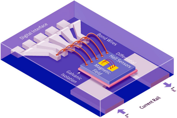
Fig. 1: A chopped dual Hall element system is precisely located over the integrated current rail. The rail itself adds typically only 600µΩ of primary resistance.
Differential dual-Hall cell technology removes magnetic offset between the two Hall measurements thus providing robustness to external magnetic fields. Galvanic isolation of up to 2.5 kV is incorporated within its package, which removes the need for optocouplers. An example using this technology provides 13-bit current resolution via SPI, with ±1.6% accuracy over life and has a measurement range of ±50A.
Current flowing through the current rail on the primary side induces a magnetic field. This is measured by two differential Hall probes (figure 2). The signal from the two Hall probes is digitalized by a Sigma-Delta-A/D converter (ADC).
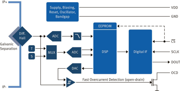
Fig. 2: A differential dual-Hall current sensor (TLI4970) incorporates galvanic isolated silicon. Independent temperature and mechanical stress sensors continuously monitor environmental conditions and feed data to a DSP for compensated current calculation.
After the programmable digital low-pass filter, the raw current signal is fed into the DSP. The differential measurement principle of the magnetic field provides a very good suppression of any ambient magnetic stray fields. For optimal accuracy despite accumulated mechanical stress through aging and temperature variation, temperature and stress sensors located as close as possible to the Hall plates monitor these variables and feed data to the DSP for compensation based on stored memory values.
For fast overcurrent detection, the raw analog signal from the Hall probes is fed into a programmable comparator. This comparator has a programmable glitch filter to suppress fast switching transients in the signal and avoid false triggers. The open-drain output of the OCD-Pin also allows readout of overcurrent signals for several of these sensors using only one microcontroller input pin.
The overcurrent detection (OCD) levels can be programmed via a Serial Inspection and Configuration Interface (SICI) in three amp steps, and stored in EEPROM. When a shunt is used in this way, continuous monitoring and calculation by the microcontroller is required. Independent temperature (T) and stress (S) sensors are located near the Hall cells, and are calculated in a parallel path to compensate the raw current signal according to internally stored calibration tables.
Use Cases
Many different use cases benefit from both the negligible impact on power and overall accuracy of differential dual-Hall current sensors. In high-current battery chargers, for example, the power dissipation of shunt-based methods is inherently inefficient.
In motor drives, the current consumption of motors and actuators is affected by the loads they are used to move or displace. Motor or actuator load correlation applications monitor the current to drive from or hold their position. More current will be required to turn a screw full of seed or drive fluid from a full vat through a valve. This current consumption can also provide very accurate measurement of mass and volume if adequate resolution is available. The shunt again requires far too much power dissipation to achieve high resolution over ±50A, and, by design, a core-based Hall Effect solution will likely suffer offset changes over time in addition to the influences of package stress and temperature.
A third use case applies renewable energy generation (see figure 3). International norms for power grid feeds limit offset in the applied AC sine wave. The limit imposed is dependent on the nation's regulating body, but it is not unusual to see requirements below 100mA for a 15A sine wave over some seconds.
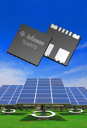
Fig. 3: Accurate current measurement is critical to achieving regulatory
compliance in renewable energy generation systems.
In this application accurate current measurement of the control loop from dc/dc converter to dc/ac inverter is essential for compliance, and power robbing shunts are the antithesis of the system's goals. An ideal solution is a coreless differential sensing technology with galvanic isolation.
About the Author
James Sterling is a principal engineer and manager of the integrated sensors business for Infineon Technologies North America. Prior to joining Infineon in 2007, he worked in product development roles with suppliers of magnetic sensors for automotive and industrial applications and in engineering roles at the National Superconducting Cyclotron. James holds degrees in Physical Science and Physics from Michigan State University.
Related Articles
New Magnetoresistive Current Sensor Improves Power Electronics Performance
Top Five Advantages of Reed Switch Technology for Low-Power Metering Applications
MDT Delivers High-Performance and Ultra-Low Power TMR Sensors as Alternatives to Hall Effect Sensors
Magnetic Field Sensor Market worth $2.9 Billion by 2020
Thermistors As Accurate Temperature Sensors Part 1: Introduction and Methods
Magnetic Sensors Find Opportunities in Green Energy