
Electric motors employ various methods of position sensing. Optical encoders, for instance, have long been favored by motor control system designers for their accuracy, and their standard ABI outputs are easily handled by today's microcontrollers. But contactless magnetic position sensors are changing that.
There are a number of reasons why contactless sensors are the preferred choice for designers. For one, magnetic position sensors are small and they are immune to contaminants such as dust, grease, and moisture. Applications in which size and/or reliability are important find many benefits from using magnetic position sensing. Until recently, however there was one sticky point working against conventional magnetic position sensors in motor design: accuracy.
New brushless DC (BLDC) motors generally have high efficiency goals for power consumption. At the same time, designers are tasked with increasing the torque of new motors, since this enables operation at lower speed to support a direct drive system. As a result, they can eliminate the need for a gearbox, thus dramatically reducing bill-of-materials (BoM) cost.
For maximum torque and efficiency, BLDC motors require extremely accurate data on the rotor's angle of rotation while turning at high speed. But this has been difficult to achieve with conventional magnetic position sensors. Now a breakthrough in sensor design is enabling the production of a new generation of devices that can capture almost perfect angle measurements, even at high rotation speeds.
How Angle Measurements Are Used
A BLDC motor consists of a rotating permanent magnet (the rotor) and three or more equally spaced fixed windings (stators). By controlling the current in the stators' windings, a magnetic field of arbitrary direction and magnitude can be produced. Torque results from the forces of attraction and repulsion between the rotor and the stator field acting on the rotor shaft. Torque is maximized when the stators' magnetic field is orthogonal to the magnetic field of the rotor's magnet. Measurement of the rotor's angular displacement provides feedback to the system which controls the current through the stator windings (see Figure 1), to enable the generation of an orthogonal magnetic field.
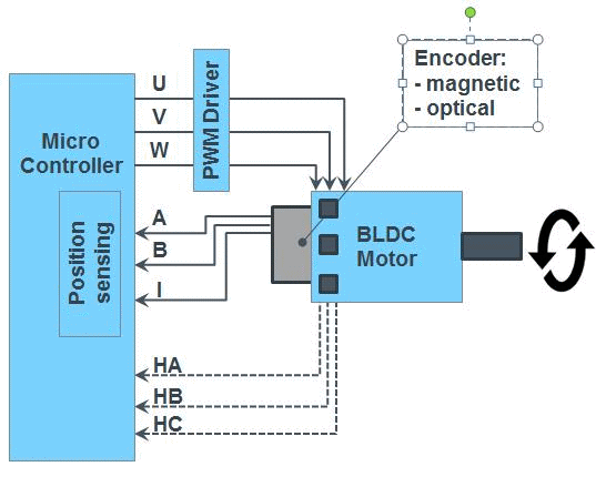
Fig. 1: A BLDC motor control system requires a closed feedback loop using measurements of the rotor's angular displacement captured by a magnetic (commonly in automotive applications) or optical (commonly in industrial applications) position sensor.
In the most advanced applications, the BLDC motor is being superseded by the permanent magnet synchronous motor (PMSM). The PMSM replaces the block commutation scheme found in BLDC motors, which suffers from torque ripple, and switches smoothly between the coils (see Figure 2). The result is less vibration and greater efficiency.
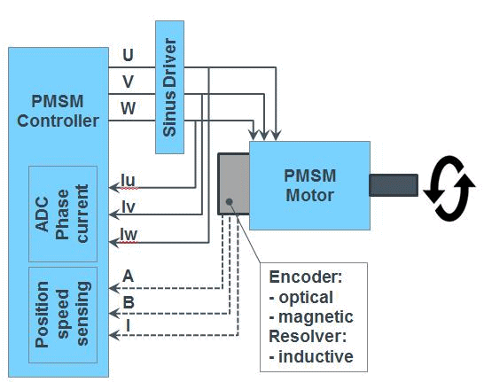
Fig. 2: A PMSM draws on a similar feedback loop to a BLDC motor's.
Industrial and automotive motor designs often are optimized for efficiency and reliability, many other motors, particularly in consumer products, put more emphasis on cost. For simple motors, an array of discrete Hall switches provides an adequate method of position measurement, producing moderate torque and smoothness. But the precision and accuracy of a Hall switch array cannot meet the torque and efficiency requirements of high-performance motors.
In contrast, a magnetic position sensor – a semiconductor with Hall sensors integrated into the silicon die – produces precise, high-resolution position data. It offers high accuracy when the rotor shaft is stationary or is turning at low speed. Unlike the optical encoders commonly used in industrial applications, a magnetic position sensor is immune to contamination and occupies little space.
Most Hall sensor ICs, however, suffer from two important drawbacks:
- Dynamic angle error at high rotation speed, a phenomenon caused by propagation delay
- A requirement for shielding in environments subject to stray magnetic fields
These limitations increase system cost and impair performance. The dynamic angle error must be compensated, which requires high-performance processing capability. Additional shielding to protect the IC from stray magnetic fields adds to the hardware BoM.
The Cause Of Dynamic Angle Error
A Hall sensor IC works by continually sampling the strength of the magnetic field generated by a magnet on the rotor shaft. The IC is mounted in a fixed position with its surface parallel to the surface of the rotating magnet, typically with a 1 mm to 2 mm air gap separating them.
The IC contains a signal conditioning and processing circuit which converts the magnetic field strength measurements into a calculation of the rotor's angular displacement (in degrees). The time taken to perform this conversion is the IC's fixed propagation delay (see Figure 3). The duration of the delay differs from one IC to another, but those on the market today have propagation delays ranging from 10 µs to 400 µs.
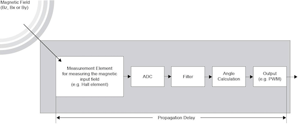
Fig. 3: Signal processing in magnetic position sensors causes propagation delay.
Propagation delay is problematic because it causes dynamic angle error when the rotor is turning. This dynamic angle error increases with speed at a linear rate; the higher the propagation delay and the speed, the greater the dynamic angle error (see Figure 4).
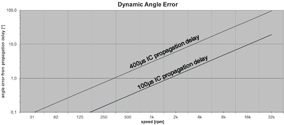
Fig. 4: there is a linear relationship between dynamic angle error and speed of rotation.
Figure 5 shows how dynamic angle error arises. Assume that the IC captures field strength measurements when the rotor's position is indicated by the red line. Assume also that the rotor is turning, and that the IC's propagation delay is 100 µs.
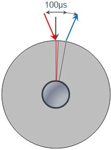
Fig. 5: How propagation delay gives rise to dynamic angle error.
By the time the IC has converted the field strength sample into an angle calculation, the rotor will have turned for 100µs to the position marked by the blue line – but the IC will tell the motor control ECU or MCU that the rotor is at the red line.
Without compensation, the commutation scheme will therefore apply current to the stator windings optimized for the red-line position, not for the blue-line position. As a result, the system fails to maximize torque, energy is wasted and the system's efficiency is reduced. If the propagation delay of the IC is 100 µs and the motor is spinning at 1,000 rpm, the dynamic angle error is 1.2°. Increasing the rotor's speed to 10,000 rpm increases the dynamic angle error to 12°.
Propagation delay is a feature of all magnetic position sensors, so system design engineers apply compensation algorithms to reduce the size of the dynamic angle error. Unfortunately, applying compensation to thousands of samples each second places a great burden on a host ECU, and can even require the addition of a dedicated error-compensation MCU. The additional BoM cost is in itself undesirable, but so too is the call on the design team's time to develop, test, and debug the compensation algorithm.
New Sensor Eliminates Dynamic Angle Error
As described above, the propagation delay of a magnetic position sensor is fixed, and the value of the dynamic angle error is determined by the duration of the propagation delay and the speed of rotation. Now a new, patent-pending method for implementing this form of compensation scheme internally in the magnetic position sensor itself has been developed by sensor manufacturer ams.
Called dynamic angle error compensation (DAEC), this internal compensation technology is available first in the ams 47 series of magnetic position sensors (see Figure 6). In the AS5147, an automotive position sensor, DAEC reduces the apparent propagation delay to 1.9 µs. This means that the dynamic angle error of measurements from the AS5147 at 14,500 rpm is a negligible 0.17°.
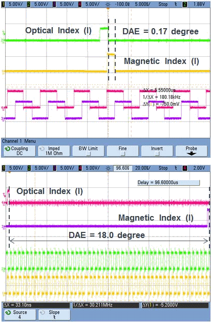
Fig. 6: Outputs from sensors with (top) and without (bottom) integrated compensation.
The difference between the measurement output of the AS5147 (left) and the output of a conventional magnetic position sensor (right) is shown in Figure 7.

Fig. 7: The figure shows on the left side the traditional discrete approach to dynamic angle error compensation. On the right side is the new integrated dynamic angle error compensation approach.
A precise optical encoder's output is shown as a reference. The sensor output shown on the right is subject to a propagation delay of 200µs, producing a dynamic angle error of 18° at a speed of 14,500rpm.
The negligible error of the AS5147, by contrast, means that its signals can be used directly by a commutation controller, with no external compensation. In fact, the internal compensation provided by the DAEC technology produces a smaller dynamic angle error than is possible with external compensation, due to the sampling error typically found in ECUs and MCUs. Internal compensation in the sensor also reduces system cost, since no additional MCU is required to perform error compensation, or a less powerful ECU can be used (see Figure 7).
Stray Field Immunity
The other drawback of many magnetic position sensors is their sensitivity to stray magnetic fields. Interference from magnetic fields other than that of the rotor magnet randomly corrupts many ICs' angle measurements, and this random error cannot be compensated by the host ECU or MCU. Users are therefore obliged to shield the IC. This raises BoM and assembly costs; it might also compromise the mechanical design in a space-constrained application.
With the application of the ISO 26262 functional safety standard to vehicles, the requirement to design immunity to magnetic stray fields into motor systems has become mandatory. Patented differential-sensing technology implemented in all magnetic position sensors from ams including the 47 series, however, provides for immunity to stray magnetic fields up to a value of 25,000 A/m. This technology eliminates the requirement for shielding from stray fields below this 25,000-A/m threshold.
Conclusion
DAEC technology enables BLDC motor and PMSM manufacturers to use extremely accurate position data and consequently maximize torque even in high-speed applications while gaining the size and reliability benefits of using a magnetic position sensor. DAEC is available today in the AS5147 (single-die) and AS5247 (dual redundant dies) automotive magnetic position sensors (AEC-Q100 grade 0 automotive qualified) to support BLDC motor co-mutation in automotive applications such as electric power steering (EPS), transmission (gearbox, actuator), pumps, and brakes. For industrial applications, the AS5047D with DAEC is also available, offering decimal ABI outputs to provide an ideal like-for-like replacement for optical encoders.
Summary
Electric motors employ various methods of position sensing. Optical encoders, for instance, have long been favored by motor control system designers for their accuracy, and their standard 'ABI' outputs are easily handled by today's microcontrollers. But contactless magnetic position sensors are changing that.
There are a number of reasons why contactless magnetic position sensors are the preferred choice for designers. For one, magnetic position sensors are small, and they are immune to contaminants such as dust, grease and moisture. Applications in which size and/or reliability are important, there-fore, realize many benefits from using magnetic position sensing. Until recently, however, there was one sticky point working against conventional magnetic position sensors in motor design: accuracy.
New BLDC motors generally have high efficiency goals for power consumption. At the same time, designers are tasked with increasing the torque of new motors, since this enables operation at lower speed to support a direct drive system. As a result, they can eliminate the need for a gearbox, dramatically reducing bill-of-materials (BoM) cost.
For maximum torque and efficiency, a BLDC motors requires extremely accurate data on the rotor's angle of rotation while turning at high speed. But this has been difficult to achieve with conventional magnetic position sensors. Now a breakthrough in sensor design from ams is enabling the production of a new generation of devices that can capture almost perfect angle measurements, even at high rotation speeds.
About the Author
Roland Einspieler has worked as a product manager for automotive magnetic position sensors with his main focus on new product definition since the start of 2014. Previously he had worked as an applications engineer for three years, supporting customers using magnetic position sensors. He started at ams in 2004 as an evaluation engineer developing high-voltage ASICs. Roland holds a degree in electrical engineering.
For further information:
ams AG
Roland Einspieler, Product Manager
Tel: +43 (0) 3136 500 31691
[email protected]
Related Articles
Peel-N-Stick Sensors Expand Reach of Internet of Things
Temperature Measurement Accuracy Demands Equal Attention to Sensors and Instrumentation