
|
Still, tire pressure is not something that most noncommercial drivers frequently check and correct. Perhaps they need a reminder along the lines of the fuel, oil, battery charge, and temperature gauges on the dashboard. In fact, Congress has passed a bill, the TREAD Act [1], which empowers the National Highway Traffic Safety Administration to develop a standard for low tire pressure monitoring that will be mandatory for any vehicle sold in North America beginning in 2004. Overseas automakers, while not required to comply, are expected to do so in response to consumer demand for safety and fuel efficiency measures.
Tire pressure monitoring systems (TPMS) were implemented a few years ago as a factory-installed feature on high-end vehicles only. Extending the technology to mid-range, higher volume production models will require that the systems be more cost effective. Not only must the bill of material be rethought, but also the entire system architecture must be redesigned for ease of integration with other systems in the vehicle and for efficient production flow. The semiconductor industry will play a leading role in this cost reduction effort.
TPMS Overview
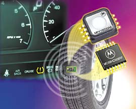
The sensor must be located in the tire if it is to perform real-time interior air pressure monitoring (see Figure 1).
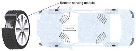 Figure 1. Tire pressure monitoring requires a distributed system: one remote sensing module inside each tire and a receiver module that brings the information to the driver information interface. |
The information must be wirelessly transmitted to the driver, typically via RF, and displayed in the cabin of the vehicle. The remote sensing module consists of a pressure sensor, a signal processor, a temperature sensor that compensates pressure variations due to temperature changes, and an RF transmitter. The system is powered by a battery with embedded intelligence that prolongs its operating life. Because battery replacement is out of the question, and replacing the entire module is not a cost-effective option for the average car owner, most of the existing specifications require up to 10 years of battery life.
The receiver can either be dedicated to TPM use or shared with other functions in the car. For instance, the receiver controller could be the existing dashboard controller or the body controller. Or the receiver itself could be shared with the remote keyless entry (RKE) system since both systems are using the same frequency range. This "functional sharing" feature helps with the system cost, reduces design cycle time, and makes the TPMS easier to integrate into the automobile.
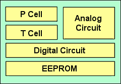
Remote Sensing Module (RSM)
|
|
The pressure sensing cell is capacitive and requires a capacitance-to-voltage conversion stage. In addition to analog functions, CMOS technology allows higher levels of integration such as digital processing possibilities. Examples are the sensor's built-in nonvolatile memory that stores calibration data, and an A/D converter that allows serial measurement reading by the microcontroller.
The sensor's internal state machine manages four different modes:
• Standby. All analog and digital blocks are switched off except for an internal low-frequency oscillator that sends a wakeup pulse over an output pin to the controller periodically (e.g., every 6 s).
• Pressure measurement. The pressure cell and the capacitance-to-voltage converter are activated.
• Temperature measurement. The temperature cell (a positive temperature coefficient resistor) and its conditioning block are activated.
• Read. After passing through one of the two measurement modes, the measurement is stored in a sampling capacitor. The read mode activates the A/D converter and enables the controller to read the measurement serially.
These four modes are coded through two input pins controlled by the microcontroller. The coding is chosen so as to make the standby mode (in which both the sensor and the controller are asleep) coded with logic zero on both pins.
|
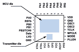
This HC08 version is well suited to the TPMS application in terms of computing power, I/O resources, and power consumption. Furthermore, the 2 KB of user flash memory with an embedded charge pump allows designers to implement the software routines necessary to address the TPMS's functional requirements. This software-based approach provides more flexibility and is more cost effective than a discrete or ASIC-based solution.
The RF transmitter is phase-locked-loop (PLL)-based, addressing both ASK (amplitude modulation) and FSK (frequency modulation). Its transmission rate is configurable up to 9600 baud. With a reference quartz oscillator of 13.56 MHz, the PLL is able to generate 315, 433, and 868 MHz carriers to cover the frequencies used in various countries.
Because the microcontroller chip is fabricated in a standard CMOS technology, and a BiCMOS process is used for the PLL transmitter, a monolithic approach is not possible today. These two technologies will converge in the near future, opening the way to a single-chip solution.
System Architecture. The TPMS sensor is designed to work in full concert with the controller, allowing some of the functions, such as power management, to be shared (see Figure 4).
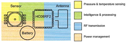 Figure 4. Power management is optimized by having it shared by the sensor and the microcontroller. |
When the sensor is set in standby mode, its internal low-frequency oscillator periodically wakes up the controller. After each wakeup, the controller may run different and configurable tasks according to the software program. Between two wakeup pulses, the microcontroller is in the stop mode. All functions are disabled to minimize power consumption, and only an external stimulus can wake the micro up again.
To improve battery management, an inertial switch can be used to detect the parking mode. In fact, in parking conditions the RF transmissions can be stopped or greatly reduced. This switch can be either micromachined silicon and integrated with the sensor, or an electromechanical external device. Parking mode detection reduces the data collision risk between RKE and TPM transmissions and also addresses the issue of radio band pollution by minimizing transmission of useless information.
The RF circuitry is designed for optimal use with the HC08. The data transmission uses register transfer techniques to minimize the CPU effective time used, thus minimizing power consumption. Demonstration designs have shown that a simple printed antenna, though far from the wavelength in dimensions, reliably attains the necessary radiated power to reach the receiver module.
Because it is mounted in the tire, the remote sensing module must be as small and lightweight as possible—an oversized module could result in wheel imbalance. This mechanical requirement is addressed by the use of a highly integrated system based on only two components and a small battery.
To differentiate themselves in the market, TPMS suppliers may offer variations of the basic techniques. The primary advantage of a microcontroller-based architecture lies in the software and is the major differentiator between manufacturer A and manufacturer B, even if both are using the same "standard" set of components. This approach allows significant cost reductions not only in the bill of material, but also in terms of development cost. Furthermore, upgrading or adding functionality becomes easier since software modifications require less development and qualification work.
The Receiver
The RSM is a relatively new concept requiring a significant innovative effort, but the RF receiver is based on techniques used for a number of years in the RKE system. Both RKE and TPM can share the same receiver because both use the same transmitting format. In fact, the HC08RF2 discussed earlier is also widely adopted in RKE systems for signal transmission from the key. Such reuse greatly reduces the function cost, but at the same time requires a more in-depth knowledge of high-level systems architectures.
In most architectures, the receiver is integrated within the body controller, which might have many other functions to supervise. CPU time-sharing between the different functions is therefore vital. The TPM function must use as little CPU time as possible; to achieve this, a highly integrated RF receiver is required.
The MC33591, also called Romeo II (see Figure 5), has been designed to provide a comprehensive RF link that is integrable in RKE and TPM systems with Romeo II at one end and the HC08RF2 at the other.
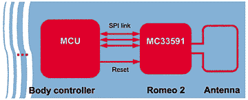 Figure 5. The RF data are decoded by the receiver, meaning that the microcontroller processes only valid RF frames. |
Thanks to its embedded RF decoding and data registers, Romeo II minimizes communication with the receiver microcontroller. The MCU is not called upon until a valid data frame is received, validated, and stored by the Romeo II. Moreover, the receiver remains fully configurable by the microcontroller through its serial link.
Tire Identification
The information conveyed by the TPMS could be more or less comprehensive, depending on the system's level of complexity. For example, the exact tire pressure value or a simple binary warning of pressures outside a preset safe operating range could be displayed. At the other extreme, the simplest system configuration does not identify each tire individually but rather only advises to check tire pressure.
Tire ID can be achieved in two ways. The simplest is manual initialization performed in the factory or the garage each time a tire is replaced or moved (e.g., rotated). The second way is automatic identification whereby the system locates each tire automatically by a learning procedure that is activated either regularly or upon request.
Manual Initialization. Each RSM sends its individual identifier with the transmitted data. During the initialization procedure, the receiver stores the four identifiers (five, if the car's spare tire carries an RSM). The operator then tells the receiver to which wheel each identifier belongs (i.e., right front = RF, right rear = RR, etc.) by means of a programming interface. This interface is commonly connected to the receiver module or a data bus, or by generating a transmission from each RSM remotely. In the latter case, the operator puts the receiver in the initialization mode and activates the transmission successively on the four RSMs in a preset order known by the receiver. Since the RSM is not directly accessible, it could be activated manually through a magnetic coupling for example.
Automatic Identification. For manual initialization, car owners must go to an authorized garage for the ID initialization—or do it themselves. The automatic method sidesteps these hassles. As might be expected, auto ID requires additional features and a smarter control unit, both of which affect the price of the system. Efforts on the part of TPMS manufacturers to implement auto ID at a minimum cost have resulted in a huge amount of intellectual property and a number of patents. Here are a few examples.
• Dedicated RF receiver for each wheel. Placing a receiver near each wheel allows the control unit to easily identify and locate each tire. The receivers must be connected to the control unit through dedicated wires or a bus. Although this is probably the most immediate and reliable solution, its high price has kept it out of all but high-end vehicles. A patented technique [3] for connecting four antennas to a single central receiver lowers the cost significantly. An RF multiplexer inserted between the antennas and the receiver makes the signal selection so as to identify the origin of the transmissions.
• Inertial sensing of speed. An accelerometer incorporated in each RSM is used to determine wheel speed, and the information is sent via RF to the receiver. A sophisticated algorithm combines speed readings with information from other systems (anti-lock braking, stability control, etc.), and calculates the tire position by exploiting the fact that in a curve the inner wheels rotate at a slower speed. This approach requires an additional component, an accelerometer. On the other hand, the sensor could be used to optimize the power consumption at the RSM level by adapting the RF transmission periodicity to the car speed, and setting it to the minimum in the parking mode. The learning procedure is long because it is based on statistical processing, and it is unreliable since it is active in road turns only.
• Amplitude analysis of the RF signals. In driving conditions, the reception level of each RSM signal by the receiver varies periodically according to the tire's rotation. This variation causes an amplitude modulation that could be detected at the receiver level and the wheel speed then deduced. An algorithm similar to that used in method 2 calculates each tire position. This solution seems very cost effective, yet its feasibility has not been demonstrated.
• Bidirectional RF links. This solution allows an immediate and reliable identification. An additional benefit is that since the receiver can communicate with each RSM, the power management could be greatly improved. In fact, while in standard one-way RF transmission, the RSM is totally deaf and transmits the pressure measurements periodically and asynchronously from the other RSMs. A bidirectional RF link enables RSMs to send their readings only upon request, avoiding collisions and making for better power management.
There may very well be other ways of automatic tire identification, but until the feature goes into mass production in the next generation of TPM systems, each system supplier is certain to closely guard its own unique technique. To date, there is no way to implement a reliable automatic ID method without generating additional cost. The market will decide whether this feature is in fact affordable.
Media Protection
The operating environment of a TPMS features such delights as temperatures of –40°C to 150°C; an atmosphere full of corrosive chemicals and abrasive dust; and acceleration forces of 1000 g, cresting at 2000 g. The sensor is by far the most exposed component in the module because it must be in contact with air to monitor the surrounding pressure. Special care therefore goes into designing the module's mechanical housing.
Most of the existing media protection solutions are implemented at the module level because they are designed for sensors with standard packages. Motorola has integrated this protection into the sensor package [4], offering manufacturers easier mechanical integration and lower system cost since no additional protection is required at the module level.
The media protection is based on a Teflon filter sealed onto the package. Extensive testing indicates that this concept efficiently protects the sensor die against any chemical that could be expected in a tire—mounting paste, moisture, and humidity. The filters are manufactured to be both hydrophobic and oleophobic (water and oil resistant), and the filter's microporous structure repels liquids and vapors while allowing the passage of gases.
For the Future
The next generation of TPMS will have a new and different set of requirements. While the technology clearly appears headed toward becoming standard equipment, these systems will most likely offer an increasing number of features in accordance with the auýomotive industry's increasing emphasis on safety. Adding more sensors or components may not necessarily be the way to provide all these additional features. Combining different information sources could be that path. TPM is surely destined to become more integrated into the vehicle architecture. New synergies similar to that discovered between RKE and TPMS will be generated, leading to more interaction with other systems such as braking or stability control.
Furthermore, the automotive industry is considering wireless links as an alternative to simplify the increasing complexity of electrical harnesses. Bluetooth technology, for example, has the interest of many of today's automakers. On this assumption, the TPMS's RF link could be integrated into a wireless general bus in the future.
According to some market projections, TPMS will explode in the coming five years. The worldwide estimated annual production rate for remote sensing modules is on the order of 100–150 million units. If these are to be battery powered, some very serious environmental issues regarding end-of-life battery recycling will be raised. Alternative batteryless solutions based on inductive coupling are therefore being investigated. This approach would also help solve the tire identification problem.
Although few specialized manufacturers are currently playing a leading role in TPMS development, their work is important because they are shaping the future for this application. With their system-level expertise and technology leadership, they will enable the car manufacturers to be more actively involved in the design and technology choices. The reality of the assumptions noted above hinges on the major architecture choices. Such decisions are ultimately up to automakers because those choices affect the entire car design.
References
1. Transportation Recall Enhancement, Accountability, and Documentation (TREAD) Act, Section 12, "Tire pressure warning."
2. B. Gogoi et al. 2000. "Integrated CMOS Capacitive Pressure Sensor," Patent Pending.
3. N. Normann et al. March 2000. "Process for evaluating the signals from a tire pressure monitoring system," U.S. Patent No. #6,034,597.
4. Ibid.