
Flow sensors are used to measure both gas and liquid flows in many monitoring and control applications. Flow can be variously defined (e.g., mass, volume, laminar, turbulent). The amount of a substance flowing (mass flow) is usually the one of interest, and if the fluid's density is constant, a volume flow measurement is generally the easiest to perform. Some technologies work for both gas and liquid flow; others are specific to what they are measuring.
Flow rate is typically obtained by first measuring the velocity of a fluid in a pipe, duct, or other structure and then multiplying by the known cross-sectional area at the point of measurement. This article will examine nine of the most commonly used technologies and devices used to measure gas and/or liquid flow.
1. Thermal Anemometers
Thermal (or "hot wire") anemometers operate on the principle that the amount of heat removed from a heated temperature sensor by a flowing fluid can be related to that fluid's velocity. These sensors typically use a second, unheated temperature sensor to compensate for variations in the air temperature. Hot wire sensors are available as single-point instruments for test purposes, or in multipoint arrays for fixed installation. These sensors are better than differential pressure types for low airflow measurements, and are commonly applied to air velocities from 50 to 12,000 fpm.
2. Differential Pressure Sensors
Differential pressure flowmeters are the most common type of unit in use, particularly for liquids. Their operation is based on the concept that the pressure drop across the meter is proportional to the square of the flow rate. The flow rate is found by measuring the pressure differential and taking the square root.
These devices, as do most flowmeters, have two elements. The primary element causes a change in the kinetic energy, creating the differential pressure in the pipe. The unit must be correctly matched to the pipe size, flow conditions, and the properties of the liquid being measured. In addition, the element's measurement accuracy must be good over a reasonable range. The secondary element measures the differential pressure and outputs a signal that is converted to the actual flow value.
For airflow measurements, common differential pressure flow devices include pitot tubes (Figure 1)
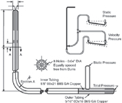 Figure 1. The pitot tube |
A pitot tube consists of two tubes that measure pressure at different locations within a pipe. One tube measures static pressure, usually at the pipe wall; the other measures impact pressure (static pressure plus velocity head). The faster the flow rate, the larger the impact pressure. Pitot tubes use the difference between impact and static pressure to calculate flow rate. Pitot tubes are low-cost, but their drawback is that they measure flow only at a single point and must be installed at the point of maximum flow. Changes in velocity profile can cause major errors. They are also prone to clogging. Averaging pitot tubes have several ports for measuring flow at multiple locations, which makes it possible to take changing velocity profiles into account (Figure 2).
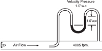 Figure 2. Velocity pressure measurement with a U-shaped tube manometer |
Some differential pressure-based flow measurement systems include transmitters that can electronically extract the square root of the measured pressure and provide a signal that is linear with respect to velocity. Others provide a signal proportional to measured pressure and depend on the control system to calculate the square root. Once the velocity is obtained, flow can be found by multiplying by the cross-sectional area of the duct. The range and resolution of the pressure transmitter limit the velocity range. Most differential pressure units are limited to a minimum velocity in the range of 400–600 fpm. Maximum velocity is limited only by the sensor's durability.
To measure liquid flow, differential pressure flow devices typically measure either velocity pressure (insertion tube type), or the drop in pressure across a known restriction. Orifice plates, flow nozzles, venturis, and pitot tubes are types of restrictions commonly used.
Insertion tube sensors typically consist of a tube with multiple openings across the width of the flow stream that give an average of the velocity differential across the tube, and an internal baffle between upstream and downstream openings that obtain a differential pressure. These meters have a low permanent pressure loss and can satisfy many common applications.
A concentric orifice plate (Figure 3) is the simplest and least costly of the differential pressure devices. The orifice plate constricts the flow of a fluid and produces a differential pressure across the plate, resulting in a high pressure upstream and a low pressure downstream proportional to the square of the flow velocity. An orifice plate usually produces a greater overall pressure loss than other flow elements.
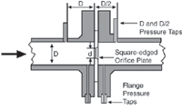 Figure 3. The concentric orifice |
Venturi tubes (Figure 4) are the largest and most expensive differential pressure devices. They work by gradually narrowing the diameter of the pipe and measuring the pressure drop that results. An expanding section then returns the flow to near its original pressure. As with the orifice plate, the differential pressure measurement is converted into a corresponding flow rate. Venturi tubes are typically used in large-diameter pipe applications requiring a low pressure drop and a high accuracy reading.
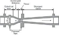 Figure 4. The venturi tube |
Flow nozzles are actually a variation on the venturi tube, with the nozzle opening being an elliptical restriction in the flow, but having no outlet area for the pressure recovery. Pressure taps are located approximately one-half pipe diameter downstream and one pipe diameter upstream.
The flow nozzle is a high-velocity flowmeter used where turbulence is high (Reynolds numbers above 50,000), as in steam flow applications. The pressure drop of a flow nozzle is between that of a venturi tube and the orifice plate (30%–95%).
Benefits of differential pressure instruments include their low cost, simplicity of operation and installation, and proven performance. It is a well-understood technology. Drawbacks can be permanent pressure loss, dirt buildup and clogging, the large size and bulkiness of some units, and their unsuitability for use with certain types of fluids.
3. Vortex-Shedding Sensors
These sensors operate on the von Kármán principle: When a fluid flows around an obstruction (bluff object), eddies or vortices are shed alternately downstream of the object. The frequency of the vortex shedding is proportional to the velocity of the fluid. Single sensors are used in small ducts, and arrays of sensors are applied to larger ducts, as with the other types of airflow measuring instruments. They are commonly used with air velocities in the 350–6000 fpm range, and are equally suitable for flow rate or flow total measurements. Use with slurries or high viscosity fluids is not recommended.
4. Positive Displacement Flow Sensors
These flow measurement devices are used where high accuracy at high turndown (ratio of the full range of the device to the minimum measurable flow) is necessary and some permanent pressure loss will not cause excessive energy consumption. They operate by separating liquids into measured segments and then moving them on. A connecting register then counts each segment. They are useful for viscous liquid flows or where a single mechanical meter is needed. Common types of positive displacement flowmeters include lobed and gear-type, nutating disk, rotary-vane, and oscillating piston meters. The meters are typically made of metals such as brass, bronze, and cast iron, but can also be constructed of engineered plastic, depending on the application.
Because these sensors require close tolerances between their moving parts, suspended solids in the flow stream can cause mechanical problems. The meters are available with flow indicators and totalizers that can be read manually. The devices are relatively costly.
5. Turbine-Based Flow Sensors
Turbine- and propeller-type meters use the principle that liquid flowing through the turbine or propeller will cause the rotor to spin at a speed directly related to flow rate. Electrical pulses can be counted and totaled. These devices are available in full-bore, line-mounted versions and insertion types where only a part of the flow being measured passes over the rotating element. Turbine flowmeters, when properly specified and installed, offer good accuracy, especially with low-viscosity fluids. Insertion types are used for less critical applications. They are often easier to maintain and inspect because they can be removed without disturbing the main piping.
6. Mass Flowmeters
Mass-related processes such as chemical reactions and heat transfer that require more accurate flow measurements have led to the development of mass flowmeters. A number of designs are available, but the most common is the Coriolis meter, based on a phenomenon called the Coriolis force. Coriolis meters are true mass meters that directly measure the mass rate of flow, as opposed to measuring volume flow. Since mass does not change, the meter is linear without needing adjustment for variations in liquid properties. Moreover, the devices do not require compensation for changing temperatures and pressure conditions. These meters are particularly useful for measuring liquids with a viscosity that varies with velocity at given temperatures and pressures.
Coriolis meters are available in various designs. One popular device consists of a U-shaped flow tube enclosed in a sensor housing connected to an electronics unit. The sensing unit can be installed directly into any process, and the electronics unit can be located up to 500 ft. from the sensor. Inside the housing, the tube is vibrated at its natural frequency by a magnetic device at the bend of the tube. This is similar to the vibration of a tuning fork, covering <0.1 in. and completing a full cycle ~80 times/s. As the fluid flows through the tube, it is forced to take on the tube's vertical motion. This in turn causes the fluid to exert a force on the tube, causing it to twist. The amount of twist is directly proportional to the mass flow rate of the liquid flowing through the tube. Magnetic sensors on either side of the flow tube measure internal velocities, which change as the tube twists. The sensors feed the information to the electronics unit, which processes and converts it to a voltage proportional to mass flow rate. This flowmeter has a wide range of applications, from adhesives and coatings to liquid nitrogen.
7. Electromagnetic Flow Sensors
Operation of these sensors (Figure 5) is based on Faraday's Law of electromagnetic induction, which says that a voltage will be induced when a conductor moves through a magnetic field. The liquid is the conductor, and the magnetic field is created by energized coils outside the flow tube. The voltage produced is proportional to the flow rate. Electrodes mounted in the pipe wall sense the induced voltage, which is measured by the secondary element.
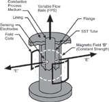 Figure 5. The magnetic head flowmeter |
Electromagnetic flowmeters are used to measure the flow rate of conducting liquids (including water) where a high-quality, low-maintenance system is needed. The cost of magnetic flowmeters is high relative to that of other types, but their important uses include measuring difficult and corrosive liquids and slurries, and reverse flow measurement.
8. Ultrasonic Flow Sensors
Ultrasonic flow sensors can be divided into Doppler sensors and transit (or time-of-travel) sensors. Doppler sensors measure the frequency shifts caused by liquid flow. Two transducers are mounted in a case attached to one side of the pipe and a signal of a known frequency is delivered to the liquid to be measured. Bubbles, solids, or any other discontinuities in the liquid cause the pulse to be reflected toward the receiver element. Because the liquid that causes the reflection is moving, the frequency of the returned pulse shifts proportional to the velocity of the liquid.
With transit meters, transducers are mounted on either side of the pipe, such that the sound waves traveling between the devices are at a 45° angle to the direction of flow. The speed of the signal moving between the transducers increases or decreases with the direction of transmission and the velocity of the liquid being measured. A time-differential relationship proportional to the flow can be obtained by transmitting the signal alternately in both directions. One limitation of this type of sensor is that the liquids being measured must be relatively free of solids or entrained gases in order to minimize signal scattering and absorption.
Ultrasonic flowmeters are nonintrusive and their cost is moderate. Many models are designed to clamp onto existing pipe.
9. Laser Doppler Anemometers
The laser Doppler anemometer (LDA) is a widely used and well-established technique for fluid dynamic measurements in liquids and gases. The directional sensitivity and nonintrusiveness of an LDA make it useful for applications with reversing flow, chemically reacting or high-temperature media, and rotating machinery, where physical sensors might be difficult or impossible to use. This technique does, however, require tracer particles in the flow.
The main benefits the LDA offers for flow measurement include:
- 1. Noncontact
- 2. No calibration needed
- 3. Measurement distance range from centimeters to meters
- 4. Velocity range from zero to supersonic
- 5. Measures flow reversals
- 6. High spatial and temporal resolution
The basic configuration of an LDA (Figure 6,) consists of:
- 1. A continuous-wave laser
- 2. Transmitting optics, including a beam splitter and a focusing lens
- 3. Receiving optics, consisting of a focusing lens, an interference filter, and a photodetector
- 4. A signal conditioner and a signal processor
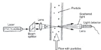 Figure 6. Laser Doppler anemometer configuration |
In general, the LDA sends a monochromatic laser beam toward the target and collects the reflected radiation. According to the Doppler effect, the change in wavelength of the reflected radiation is a function of the targeted object's relative velocity. Therefore, the velocity can be found by measuring the change in wavelength of the reflected laser light. This is achieved by forming an interference fringe pattern (pattern of light and dark stripes) by superimposing the original and reflected signals.
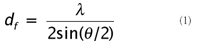
A Bragg cell is often used as the beam splitter. This is a glass crystal with a vibrating piezo crystal attached. The vibration generates acoustical waves that act like an optical grid. Two beams of equal intensity exit the Bragg cell, with frequencies f0 and fSHIFT, and these are focused into optical fibers that bring them to a probe. In the probe, the parallel exit beams from the fibers are focused by a lens to intersect in a region called the measurement volume. The light intensity is modulated due to interference between the laser beams, which produces parallel planes of high light intensity called fringes. The fringe distance df is defined by the wavelength of the laser light and the angle between the beams:
 |
Flow velocity information comes from light scattered by tiny "seeding" particles carried in the fluid as they move through the measurement volume. The scattered light contains a Doppler shift—the Doppler frequency fD—which is proportional to the velocity component perpendicular to the bisector of the two laser beams, which corresponds to the X axis of the measurement volume.
A receiver lens collects the scattered light and focuses it on a photodetector. An interference filter mounted in front of the photodetector passes only the required wavelength, removing noise from ambient light and from other wavelengths. The photodetector converts the fluctuating light intensity into an electrical signal, the Doppler burst. The Doppler bursts are filtered and amplified in the signal processor, which determines fD for each particle, often by frequency analysis using the fast Fourier transform algorithm.
The fringe spacing df provides information about the distance traveled by the particle. The Doppler frequency fD provides information about the time: t = 1/fD . Since velocity equals distance divided by time, the expression for velocity thus becomes:
It is often the case in particle seeding that liquids contain adequate natural seeding, but gases must usually be seeded. Ideally, the particles should be small enough to follow the flow, but large enough to scatter enough light to obtain a good signal-to-noise ratio at the photodetector output. The size range of particles is usually 1–10 μm. The particle material can be solid (powder) or liquid (droplets).
There's More
This article was adapted from Chapter 10 of Sensor Technology Handbook, by permission of Newnes, a division of Elsevier, ©2005. The rest of the chapter addresses flow sensor selection, calibration, installation, and maintenance; and level sensing technology. To purchase this reference work, please visit www.books.elsevier.com/computereng and use offer code 87216 to receive a 10% discount and free shipping until December 31, 2006.
William Hennessy can be reached at BMT Scientific Marine Services Inc., Escondido, CA; 760-737-3505; [email protected] , www.scimar.com.