
System designers with sensor signal-path needs typically use custom analog systems that can take weeks if not months to design. After making their initial designs, engineers need to build and test the designs, and then they are still left with the task of writing system algorithms to assure product differentiation in their markets. Now there is an easy road for sensor signal-path designers, a road that allows them to spend less time on hardware development and more time on implementing intellectual property in their end products, decreasing the time to market.
National Semiconductor has introduced a new family of integrated circuits (ICs) called sensor analog front ends (sensor AFEs) that provide an easy-to-use solution to the designer's signal-path challenges. A sensor AFE is not an IC attempting to solve the signal-path needs of all sensors; this is neither practical nor desirable.
For example, a temperature transmitter found on many industrial floors, at the end of a 4–20 mA loop, must consume very little power but its bandwidth, speed, and noise are less critical parameters. A suitable signal path for this application will provide a variable sample rate of 1–200 sps and a noise floor of 7 µVrms while not consuming more than the allotted 4 mA of current. On the other hand, a weigh scale application where the weight of an object needs to be measured very quickly as it moves across the scale will require sampling rates as high as 4 Ksps. Similarly, the larger input dynamic range of the weigh scale application justifies the need for a much lower noise floor of 15 nVrms.
National Semiconductor's sensor AFEs segment the sensor signal-path market into clusters or families of sensor applications. Sensor AFEs are optimized solutions for a particular family of sensors such as temperature sensors or weigh scales. By creating components that are optimized for a particular application, National's sensor signal path ICs offer designers an alternative to their long hardware development cycles.
In addition to meeting the technical "must have" specifications of the sensor signal path, sensor AFEs are also software-programmable via SPI or I2C, allowing them to be optimized to meet the specific needs of a particular sensor application. As an example, imagine using a thermocouple that covers a wide temperature range. Having a wide temperature range also means that the output voltage of the thermocouple will vary greatly depending on the temperature being measured. As a result, it is advantageous for the system designer to be able to dynamically adjust the gain of the signal path.
The LMP90100
National's first sensor AFE product, the LMP90100, targets precision, low-power sensor transmitter applications such as those shown in Figure 1. In the LMP90100, the system designer has access to a programmable gain amplifier with a gain range of 1x to 128x. Choosing a higher gain allows them to better use the input dynamic range of the integrated 24-bit ΣΔ ADC and results in better overall system performance and accuracy.
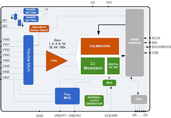 Figure 1. LMP90100 sensor transmitter AFE |
Another software-programmable feature is the input configuration. Different temperature sensor types have differing configuration requirements, for example. The LMP90100 has a fully programmable input multiplexer (MUX) that allows any possible configuration of the eight available input pins (Figure 2). Other software-programmable features include programmable current sources, multiple voltage reference options, and adjustable sample rates.
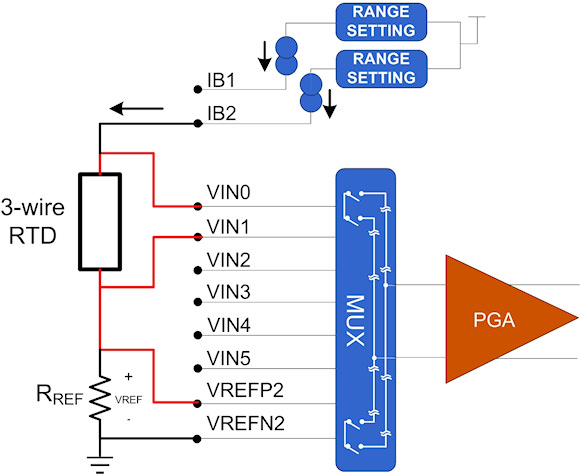 Figure 2. 3-wire RTD configuration of the LMP90100 |
Sensor AFEs also include sensor diagnostics that can test the health of sensors, a valuable feature in applications where the sensor is hundreds if not thousands of meters from the central controller. The central controller needs to periodically monitor the health of a sensor to guarantee that the information gathered is accurate. With an LMP90100 IC, you can enable current sources to provide the required sensor diagnostic function. If the sensor has a failed open, these current sources will cause the input node to float to the positive supply rail and will flag an open circuit condition. If a sensor has become shorted, the current sources will create a low-amplitude signal that is compared to a user-programmable current level intended to test for short circuits or nearly short-circuit conditions. With programmable short-circuit thresholds, it is also possible to detect sensors that are on the verge of failing. Another sensor diagnostic technique is to slightly adjust the configuration of a particular sensor AFE and monitor the sensor's output response.
Sensor transmitter nodes need to be power conscious because they are powered directly from the loop and therefore the total signal-path power consumption needs to remain below 4 mA. As a result, the optimum sample rate needs to be selected on a sensor-by-sensor basis. If one sensor needs to be sampled at 1 sps and another sensor requires multiple samples to be collected at 200 sps, the LMP90100 allows each signal path channel to operate at a sample rate independent of the others. In addition, unneeded features such as internal clock sources and current sources can be powered down to minimize power consumption.
Similarly, the sensor AFE offers advantages for applications where multiple sensors must be monitored at the same time, such as monitoring pressure over a wide operating temperature range. In contrast to custom designs that would require separate signal paths for each sensor, the LMP90100, with its flexible input MUX, can accept analog inputs from multiple sensors (Figure 3). Each sensor also involves a different signal level; the pressure sensor may have a full-scale output range of 20 mV while the temperature sensor may have a range of several volts. The LMP90100 addresses this with its programmable gain options of 1x to 128x in steps of 2x or 6 dB.
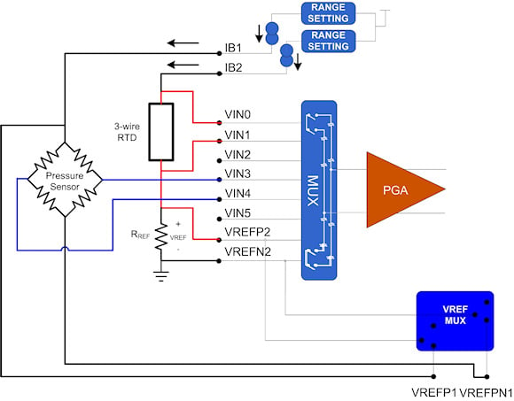 Figure 3. Temperature-compensated pressure sensor application |
Additional application requirements include biasing the sensors and providing a voltage reference to the ADC. In the case of the LMP90100, onchip current sources can be used to bias the sensors while its reference MUX lets you choose between two different voltage references for the 24-bit ADC. The reference MUX also allows for ratiometric measurements where the ADC reference is relative to the bias of the sensor, providing superior system performance in noisy environments.
Lastly, since the measurements are being made over a wide operating temperature range, traditional signal path systems will need to be characterized over the entire temperature range. With the LMP90100's true background calibration, the signal path from the output of the sensor to the input of the microcontroller is self-calibrated and does not drift over temperature or time. This feature removes the need to monitor or correct the gain and offset of the electronics in the system signal path without impacting system performance.
The LMP91000
Another multisensing application where sensor AFEs offer advantages over traditional custom designs is in a toxic gas detector where multiple gases need to be sensed with the same instrument. Some toxic gas sensors experience an oxidation reaction in the presence of a particular gas while others experience a reduction reaction. A traditional signal path for this application needs the ability to adjust the bias voltage for the transimpedance amplifier (TIA) that will be used to measure the current flowing through the sensor. For the reduction reaction where the current is flowing out of the sensor's working electrode (WE), the bias needs to be set to a positive reference value to prevent the output of the TIA from clipping near ground when the current increases.
For the oxidation reaction, the current is flowing into the sensor's WE, so the bias needs to be set near ground to prevent the TIA's output from saturating near the positive supply. Using a custom discrete design, one solution is to use bipolar supplies that allow the TIA to swing in either direction, with the TIA's inputs biased near ground. Alternatively, you can use an external DAC or analog switch to alter the bias voltage from near ground to near the positive supply voltage for a specific toxic gas sensor type. The LMP91000 (Figure 4), designed for portable toxic gas detectors, integrates a programmable bias voltage for the TIA inputs, allowing operation for both types of chemical reactions from a single positive supply voltage (Figure 5).
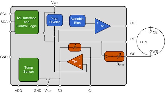 Figure 4. LMP91000 toxic gas sensor AFE |
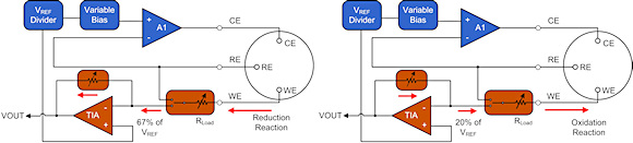 Figure 5. Different chemical reactions for the LMP91000 |
Another challenge of toxic gas detectors is the dynamic range of the currents to be detected. Some toxic gas sensors have a full-scale range of 600 µA and a sensitivity of 10 nA/ppm while others have a full-scale range of 10 µA and a sensitivity of 1 nA/ppm.
Multiple solutions exist to meet this requirement. One is to use a high-resolution 16- or 24-bit ADC rather than the traditional 12-bit ADC to provide adequate measurement resolution over a wide range of currents but at the cost of a higher-priced ADC. Another option would be to use analog switches to change the gain of the TIA by switching in different feedback resistor values. This would enable the use of a 12-bit ADC where the dynamic range of the ADC is better used to achieve the required performance. The LMP91000 uses a programmable feedback resistor from 2 kΩ to 375 kΩ with the option to switch to an external feedback resistor.
Because portable gas detectors are never fully powered down due to the long turn-on time constants of the sensors, it is critical to provide multiple modes of operation. During normal operation, the gas sensor is being monitored and power consumption is 10 µA. In standby mode, where the sensor is still being biased to allow for a quick recovery time (seconds vs. hours) but no actual measurements are made, the power consumption is 6 µA.
Finally, there is the application requirement to control the potential between the WE and the reference electrode (RE) of the toxic gas sensor (referred to as bias voltage on most sensor datasheets). Some sensors, such as carbon monoxide sensors, require zero bias, which means the RE and WE are at the same potential. However, nitric oxide gas sensors require a positive bias voltage and other types of gas sensors require a negative bias voltage. Again, you can meet the signal-path needs using a combination of analog switches, multiple reference voltages, and/or DACs or you can use the LMP91000 that meets this demand by providing a programmable bias voltage from ±24% of VREF.
Changing the bias voltage of a toxic gas sensor also changes the sensor's sensitivity. By modifying the sensor sensitivity, a central controller can detect whether the change in sensor output is appropriate for the change in bias voltage and thus identify sensors that are starting to wear out or are on the verge of failure.
Development Tools
Software and hardware development tools are available for each of the sensor AFE ICs, allowing system designers to learn how the various sensor AFEs meet their sensor signal needs. The software tools offer a user-friendly environment to learn about the specific sensor AFE IC, including a wizard index with short videos on the device's features and performance as well as explanations of the capabilities of the tool (Figure 6).
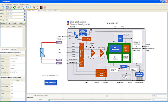 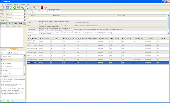 Figure 6. Virtual device tour and sensor selection |
Once you are either done with the software wizard or have bypassed it, you can choose a sensor from a sensor database to connect to the sensor AFE. For example, in the case of the LMP90100, which is designed for precision, low-power sensor transmitter applications, you can choose from a variety of temperature sensors (such as thermocouples, RTDs, and analog temperature sensors), pressure sensors, and load cells. If your specific sensor of choice is not available in the list, you can add it manually to the database.
After a sensor has been selected, the sensor AFE is automatically configured for that sensor. At this point you are led to the sensor AFE block diagram where you can investigate how the device has been configured for your chosen sensor. A Help Bar guides you through the programmable blocks of the sensor AFE and written descriptions of all the programmable blocks are available by placing your mouse over a particular block.
In addition to programming the device automatically for the selected sensor, the software tool offers estimated device performance for that particular configuration of sensor and AFE. If any device configurations are changed such as gain or sample rate, the estimated performance table will update automatically and show the new device performance. The software tool lets you learn how the part will meet your needs without having to read a lengthy datasheet.
If you are interested in investigating the performance of the sensor AFE further, you may purchase development hardware that works with the software. You can transfer all configurations to the sensor AFE evaluation board via a USB-based data capture board called the SPIO-4 (Figure 7). With the development hardware in place, you can now migrate to the measurement tab where you can compare real-world measurement data to the estimated data.
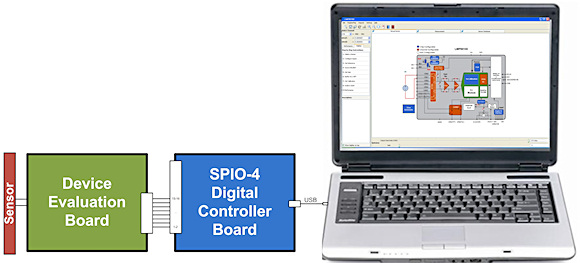 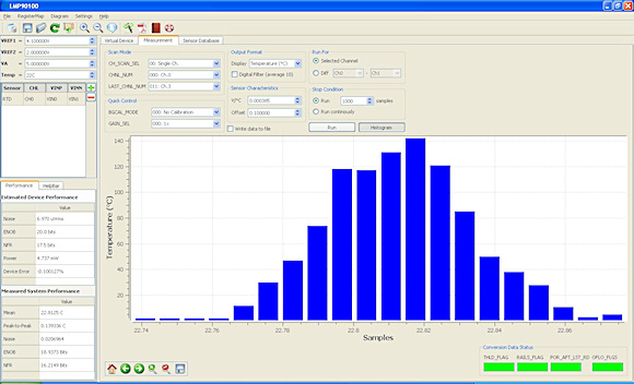 Figure 7. Development system and measurements |
Because some sensor AFEs such as the LMP90100 have multiple inputs, several sensors can be monitored at the same time. You also have the choice of monitoring the system performance in terms of voltage, ADC output codes, or sensor terminology such as °C or °F for temperature sensors. Statistical data are also available for all data collected. Data can be displayed in the time domain, emulating an oscilloscope screen shot, or in a histogram format. The development tool is just another way that sensor AFEs can provide system designers with an easier path to completing their hardware development.
Software programmable features such as the ones described above offer hardware designers several advantages over traditional custom designs. Regardless of whether you are a sophisticated analog designer or a novice system designer, sensor AFEs make design easy and accelerate your time-to-market.
ABOUT THE AUTHOR
Chuck Sins, MSEE, is a strategic applications engineer for National Semiconductor's Precision Systems organization working on sensor signal-path products. He can be reached at National Semiconductor Corp., Santa Clara, CA; 408-721-6758, [email protected].