
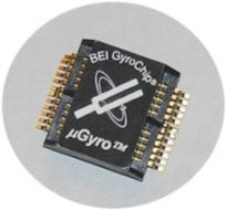
 Figure 1. The MicroGyro |
The Systron Donner Automotive (SDA) quartz MEMS MicroGyro (Figure 1) will be qualified, in the second half of 2007, for automotive engine compartment (under-hood) applications mounted on an ESC brake system ECU.
Based on a Coriolis force quartz tuning fork sensing element, the sensor is capable of meeting specifications more stringent than those required for ESC, including newly emerging Lane Keeping applications that alert the driver to inadvertent vehicle drift in the driving lane, thereby mitigating a significant cause of accidents.
This article highlights the advantages of quartz MEMS gyros over silicon gyros for use in harsh environments.
Safety-Critical Applications
Both rollover airbag and brake-stability control gyros are "safety-critical." These systems need fault detection during operation in case a key sensor generates an erroneous output. While checking sensor health at engine startup by commanding the sensor into a built-in test mode provides some confidence at the time of the test, a subsequent sensor failure during vehicle operation may result in erroneous brake or airbag activation. ECUs have software algorithms for sensor failure detection, but sensor self-monitoring adds to the overall system safety. Most applications cannot afford redundant gyros with software algorithms to determine if one of the sensors has failed. Using a single gyro with advanced self-monitoring is an alternative, lower-cost approach to providing a high level of fault-detection confidence.
A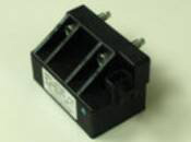 B 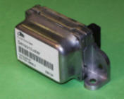 Figure 2. A yaw rate sensor (A) and a roll stability control (RSC) sensor cluster (B) |
Traditionally, ESC gyros have been mounted in inertial sensor packages inside the passenger compartment, with a typical operating temperature range of –40°C to 85°C. In the mid-1990s—the early days of ESC production—the yaw rate gyro (Figure 2A) and the lateral and longitudinal accelerometers were mounted in separate packages. These packages sent analog sensor signals to the engine compartment brake ECU via cabling.
More recently, sensors have been integrated into a single "sensor cluster" containing all the inertial sensors, power conditioning, and a CANbus interface to the ECU. The most advanced of these clusters is the RSC (Roll Stability Control) unit (Figure 2B), which includes yaw and roll rate gyros plus lateral and longitudinal accelerometers in addition to power conditioning and a CANbus interface to the ECU.
Some OEMs plan to mount the yaw rate gyro in the brake ECU where it is subjected to temperatures up to or exceeding 125°C, and may experience significant shock inputs during operation from brake hydraulic modulator action. If the environmental challenges can be overcome, this approach would save the cost of a separate sensor cluster unit and avoid the mounting and packaging costs for its interface circuits, power conditioning, connectors, cabling, and installation.
The MicroGyro
Gyros sense the rate of rotation, or angular rate, of a body to which they are attached. As a result, a primary specification of rate gyros is the maximum angular rate it can accurately sense—the "rate range"—with units of plus or minus the degrees of angle change per second (±°/s). With a single common design, the MicroGyro implements all automotive rate range requirements. Electronic stability control brake applications typically require a gyro rate range of ±75°/s while rollover airbag deployment applications typically require the highest rate measurement capability, in the region of ±300°/s to ±400°/s. The MicroGyro is capable of ±819°/s with rate error of <2°/s at 819°/s measured at 125°C. The rate output digital resolution is 0.025°/s/bit over the full ±819°/s range capability and is illustrated in Figure 3.
 Figure 3. Rate range capability |
Continuous Built-in-Test (C-BIT) (Figure 4) performs a continuous check of the operating gyro. Items checked include fork drive and pickup tines, drive oscillator, analog front end, rate signal processing, and rate output circuits. In addition to C-BIT, the MicroGyro employs 20 other monitors for further fault detection. Many of these monitors perform continuously during operation and several are conducted at gyro startup. These firmware-based monitors cover virtually every functional block in the signal processing ASIC.
 Figure 4. Continuous built-in-test diagram |
Engine Compartment Temperature. The MicroGyro uses a variety of techniques to meet the 125°C temperature requirement and prevent the gyro readings from drifting. These low-drift techniques also facilitate the long-term (aging) and temperature stability characteristics of the device. The qualities responsible for the MicroGyro's stability include:
- Stability of high-purity piezoelectric crystalline quartz
- Design of the sensing element
- increased mass for stronger Coriolis effect and reduced vibration susceptibility
- reduced micromachining process errors
- improved quadrature and piezoelectric signal strength
- Single-point fork mounting technique removes the thermal mismatch sensitivity between sensing element and mount
- ASIC designed for high-temperature operation
- Minimal use of analog circuits to avoid tendency to drift with temperature and/or age
- Digital signal processing (DSP) of the rate signal to maintain zero drift with temperature or age
- Robust calibration
- Control of package resonance effects that might shift with temperature or age
Engine Compartment Shock. The ECU application also requires operation in a shock environment that differs from the typical automotive factory handling drop-shock specification, which requires the device to function correctly after a 1 m drop to concrete. In tape and reel packaging for use in pick-and-place machines, the MicroGyro survives more than a 1 m drop to concrete. Within the ECU, the drop-shock environment is a function of how the gyro is mounted within the ECU and how shock is transmitted to the gyro by the ECU structure if the ECU is dropped. This environment is unique to each application and can be quite difficult to assess accurately.
Brake ECU hydraulic modulator operation can inject significant shock into gyros mounted in the ECU PCB. SDA specifies the operating shock environment in engineering terms to enable the ECU designer to accommodate the gyro. That preliminary specification uses a one-half sine shock pulse with 0.5 ms pulse width and 50 g pulse amplitude.
Cost-saving Benefits
Eliminating sensor clusters by packaging sensors in the brake ECU has great cost-reduction potential. An alternate cost-reduction technique is to integrate the inertial sensors into the airbag control ECU inside the passenger compartment and send ESC inertial signals to the brake ECU in the engine compartment by CANbus. By doing this, the inertial sensors operate in the more benign passenger compartment environment for almost the same cost savings.
A comparison of typical cost categories (Figure 5), where X denotes dollars of cost, highlights the savings to be achieved if the technical issues for engine compartment sensors can be overcome. By placing the gyro in the brake or airbag ECU, eliminating the sensor cluster, we eliminate the costs associated with the sensor cluster's separate housing, cabling, power conditioning, and installation.
| Parameter | Sensor Cluster | Airbag ECU | ESC ECU |
|
SC housing/connector SC power conditioning SC CAN interface SC-to-ECU cabling SC vehicle installation ECU-to-ECU CAN ECU-to-ECU cabling Sensor temperature range Operating shock environment No. of failure modes |
$X $X $X $X $X $0 $X –40°C to 85°C Low High |
$0 $0 $0 $0 $0 $X $X –40°C to 85°C Low Medium |
$0 $0 $0 $0 $0 $0 $0 –40°C to 125°C High Low |
Performance Parameters
MEMS gyro performance depends on the stability of all operating parameters. Variation with temperature is allowed, but it must be precisely repeatable from temperature cycle to temperature cycle over many years. SDA's quartz MEMS gyros use a high-purity cultured quartz crystal fabricated to its specification. Quartz stability is complemented by the patented single-point fork mount, which removes sensitivity to thermal mismatch between the fork and mount structure and to other perturbations from the surrounding packaging.
Figure 6 illustrates the bias over temperature performance of newly manufactured devices.
 Figure 6. Typical (as manufactured) bias performance |
The ultimate test of MEMS gyro stability is bias performance with age over lifetime, since significant gyro parameter drift will cause loss of calibration. A robust gyro will maintain its specifications over 15+ years, experiencing very small parameter shifts (when expressed in physical quantities) over this time. After operating in a 135°C environment for 105 hr. at 5.25 V max. power (Figure 7), the MicroGyro exhibits very small amounts of drift—the worst-case drift is 0.16°/s, 8% of a typical ESC maximum bias specification of ±2°/s.
 Figure 7. Aging bias drift characteristics |
Silicon Gyros
Despite the predicted demise of quartz gyros in favor of silicon devices, various silicon gyros exhibit characteristics that degrade performance, reliability, and ease of integration:
- Sensing element's low Q (a tendency toward damping of the vibrating sensing element) requires vibration operation in a vacuum and use of "getters" to maintain long-term vacuum
- "Stiction" issues between the moving MEMS element and the substrate
- Multiple layers (2, 3 or 4) of silicon and/or glass for sensing element, substrate, sealing cap, and ASIC integration add cost and complexity
- Potential thermal stress issues, since vibrating Coriolis masses are suspended with multiple support structures (flexures). These design-specific effects result in degraded bias and/or scale factor over temperature performance
- Susceptibility to "stone-impingement" environment when mounted on the floor pan inside the vehicle. Rocks and gravel kicked up by the wheels induce shock pulses in the gyro mounted on the other side of the floor pan. When SDA quartz gyros experience the same conditions, they withstand these induced shocks better than silicon gyros
- Additional circuits are required to emulate continuous self-monitoring, using a time-multiplexed scheme that periodically alternates between "commanded self-test" and "operate" during vehicle operation
- Additional isolation circuits are required to avoid cross talk for redundant or multiple-gyro applications on the same circuit board, such as yaw/yaw or roll/yaw. Vibrating Coriolis gyros are prone to cross talk either electronically or mechanically, with one gyro influencing the output of a neighboring gyro. The MicroGyro's use of a split-drive frequency technique eliminates this error source
- Commanded self-test on start-up does not detect failures while driving
- Some implementations of periodic commanded self-test add failure modes due to the extra circuitry
- Most silicon gyros are "Z-axis" sensing (perpendicular to mounting plane) and require orthogonally mounted daughter-boards for multi-axis applications, which add cost and potential performance issues
- Marginal performance, leading to initial market entry for some silicon gyro suppliers in the rollover airbag deployment rollover application, which has lower performance requirements
- Calibration after customer circuit board installation, causing loss of entire assembly if calibration fails
- Specifying typical parameter values with no guaranteed upper and/or lower limits
- Significant noise characteristics
MicroGyro Advantages
In addition to its ability to withstand severe environments, the MicroGyro also features X/Y axis orientation to enable two-gyro applications (redundant or orthogonal) with an in-plane mounting. This avoids the use of daughter boards on the system circuit board. Its split-drive frequency models eliminate multigyro cross talk, and it has both analog and SPI digital outputs. Two auxiliary analog inputs let the application engineer digitize other analog devices onto the SPI bus. Finally, it provides both basic gyro functionality and continuous self-test without requiring additional components.
The MicroGyro offers comprehensive performance and functionality capabilities. Several customers are currently designing this new gyro into systems while others are evaluating the device for integration into their designs.