
The mechanical response of MEMS inertial sensors (accelerometers and gyros) must be tested to verify the mechanical integrity and performance of the sensor element. One major obstacle to identifying inertial sensor defects early in the manufacturing process has been an inability to dynamically stimulate and sense the mechanical performance of the sensor at wafer level.
Instead, manufacturers have tested the sensor's static capacitance and leakage behavior. This methodology provides limited sensor characterization and cannot detect mechanical performance or process anomalies that are common in inertial sensors. Mechanical performance is therefore not fully determined until the sensor is assembled, packaged, and tested on a mechanically dynamic system such as a vibration or rate table. This is often costly and too late in the development or manufacturing process to respond to design or fabrication issues.
A Better Test Methodology
Drive Sense Technology (DST) is a test technology that can determine the sensor's mechanical behavior and response at wafer level. In contrast to conventional wafer-level test methodologies, DST dynamically stimulates and senses the mechanical movement of the sensor element (box). Sensor resonant frequency, damping ratio, –f3dB frequency, Q-factor, and spring constant are among the measurands, with significantly shorter test times than conventional methods.
Details
The STI3000 wafer-level test system consists of a mixed-signal tester (Figure 1) interfaced to a device-specific element probe card. DST is based on three signals: analog drive, tuned AC source, and conditioned output. The STI9000 ATE (automated test equipment) unit generates an analog voltage drive stimulus that is further processed by the STI3000E probe card electronics to create the final tuned AC source signal used to drive the sensor element. The probe card measures the element response and conditions the output. This signal is then further processed and digitized by the ATE response subsystem. The processed data are a representation of the sense element mechanical position vs. time during mechanical excitation. As noted above, resonant frequency, damping ratio, –f3dB frequency and spring constant are just a few of the parameters that can be obtained with DST. Figure 2 illustrates the drive signal (step function) and the resultant conditioned dynamic response signal of a typical sensor element. The element response shows an exponential decay (damped natural frequency response).
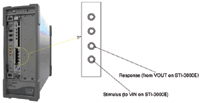 > Figure 1. The STI3000 wafer-level test system consists of a mixed-signal tester interfaced to a device-specific element probe card |
Figure 3 shows a typical DST test flow for a MEMS capacitive accelerometer. The first test measures the leakage current for each pad. High leakage currents can be caused by contamination or other processing defects.
Next, a step response test applies a DC step voltage input (positive or negative step) to the sense element and captures the mechanical position (response) of the sense element vs. time. During this test, the STI9000 test system calculates the resonant frequency, spring constant, and damping ratio from the element response data. In addition to testing the element performance, this characterization is also extremely useful for validating parametric design models.
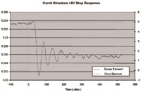 > Figure 2. The drive signal (step function) and the resultant conditioned dynamic response signal of a typical sensor element |
Following the step response test, a hysteresis test is performed in which a positive then a negative voltage ramp is applied to the sense element. The increasing voltage mechanical path is compared with the decreasing voltage mechanical path. Hysteresis, slopes, and nonuniform slope changes are captured and characterized.
The final test shown in the DST flow measures the –f3dB frequency response, which is the point where the unity gain output is attenuated by –3 dB. To accomplish this, the element is driven through a series of sinusoidal sweeps (based on digital patterns) at constant amplitude and the element output response is measured vs. time.
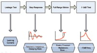 > Figure 3. A typical Drive Sensor Technology wafer-level test flow for a MEMS capacitive accelerometer |
In addition to determining the sense element's mechanical behavior, the DST methodology provides critical information about the element's structural integrity, including detection of contamination (particulates), stuck or cracked elements, and other process anomalies. The typical test time for a MEMS capacitive accelerometer DST flow at wafer level is <1.5 s/die.
Gyros Too
While DST is very useful for measuring most MEMS accelerometer sense elements, it is critical for measuring MEMS gyro sense elements. Passive wafer-level techniques (capacitive, leakage, or other static measurements) tend to be ineffective and time-consuming; a dynamic stimulus and response test methodology is required. For useful operation, gyros must be driven within a narrow bandwidth near their natural resonance. DST provides a suitable driving signal and measures the response signal from the gyro element at wafer level, providing the ability to measure the resonant frequency for the drive and sense modes as well as their Q-factor.
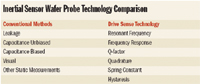 Inertial Sensor Wafer Probe Technology Comparison |
Gyros are inherently more sensitive to process variations than are accelerometers, due to the critical balance required between the driving and sensing modes of the mechanical element. Most gyro elements therefore have a very symmetric construction. Any process-induced asymmetries may cause unwanted modes or coupling, resulting in excessive noise or errors that can reduce device sensitivity. DST can determine the phase response of the drive and sense modes of the gyro element, another important gyro performance parameter.
For Design and Process
Drive Sense Technology (DST), an effective test methodology, offers improved wafer-level test performance capabilities and increased throughput for MEMS inertial sensor elements such as accelerometers and gyros. It provides the sense element's true mechanical performance, including resonant frequency, damping ratio, Q-factor, quadrature error, and –f3dB frequency response with <1.5 s/die throughput. This information is useful to element designers for validating mechanical models and optimizing the design, and to process engineers for improving the manufacturing process.
A U.S. patent is pending on Drive Sense Technology.
John J. Rychcik, MSEE; Chris S. Nickerson, BSME; Gary A. Morrell, BSEE; Marc Straub, MS; and Hongyuan Yang, MSME, can be reached at Solidus Technologies Inc., Colorado Springs, CO; 719-471-1960, www.solidustech.com. For more information, contact John J. Rychcik, 719-337-6094, [email protected].