
Adding an integrated magnetic concentrator to Hall effect sensors enables high-accuracy 360° rotary position sensing. The Triaxis Hall technology, based on integrated magnetic concentrators (IMCs), enables the development of small, cost-effective, high-accuracy, noncontact rotary position sensors. Melexis' MLX90316 is the first member of the Triaxis family and is intended to solve long-standing challenges in 360° position sensing.
How Does it Work?
Conventional horizontal (or planar) Hall sensors are sensitive only to the magnetic flux density applied orthogonally to the IC surface. In contrast, the Triaxis Hall sensor can actually sense all three components of the flux density at a single spot.
This is made possible by adding a 200 µm dia. and 25 µm thick IMC centered above a cross-shaped arrangement of two pairs of planar Hall plates. The Hall plates are the sensitive elements (Figure 1A).
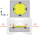 Figure 1. A top view of the Triaxis Hall sensor (A) showing the IMC (yellow) and planar Hall plates (blue). A cross section (B) along one axis of a Triaxis sensor shows the IMC and planar Hall plates and magnetic flux lines |
The IMC material is amorphous and it is deposited and structured onto the silicon wafer level using photolithography and etching techniques in a postprocessing step.
The IMC converts the flux density applied parallel to the surface of the chip (B//) into orthogonal components (B_1) that can be sensed through the Hall plates underneath (Figure 1B). The conversion is linear as long as the IMC material does not become saturated, which occurs with a parallel magnetic flux density >70 mT. If saturation occurs, the linearity of the sensor is affected but not irreversibly; linearity returns once the flux density is back in normal range. The IMC does not show hysteresis.
Each pair of Hall plates measures the orthogonal flux density applied to them directly or through the presence of the IMC structure. If we take each pair of plates and subtract the signals within them, any orthogonal component (i.e., BZ) of the flux density cancels out, leaving the only parallel components (i.e., BX and BY). Adding the signals eliminates the horizontal components; therefore only the orthogonal component is sensed. Consequently, through a simple operation, we can measure all three components of the flux density. Hence the name Triaxis Hall.
Triaxis Hall in Action
As a noncontact rotary position sensor IC, the MLX90316 uses only the parallel components of the flux density (i.e., BX and BY) as applied to the IC by a rotating magnet (sidebar).
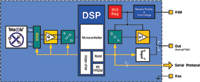 Figure 2. A block diagram of the MLX90316 |
The block diagram in Figure 2 shows that both raw Hall signals VX and VY are amplified through a multiplexed chopper amplifier prior to being digitized. A microcontroller-based digital signal processing (DSP) core further processes the signals and computes the angular information from them. The angle (α) is output as an analog signal (after passing through a DAC) or as a digital PWM or serial signal.
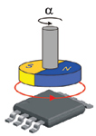 Figure 3. A diametrically magnetized magnet rotating above the IC |
When a diametrically magnetized magnet (one that is magnetized through the plane of a disk magnet) rotates above the IC (Figure 3), the flux density components BX and BY will describe two sine waves in quadrature (Figure 4) with BX proportional to cosine(α) and BY proportional to sine(α).
 Figure 4. The rotating magnet produces two sine waves in quadrature, giving the magnetic flux densities in the X and Y axes, BX and BY |
The raw Hall signals VX and VY are proportional to BX and BY. After amplification, the MLX90316's embedded DSP performs the following operation to get the angular information:
 |
where:
A = gain
VX = raw Hall signal in the X direction
VY = raw Hall signal in the Y direction
α= angle
Because the MLX90316 directly provides the angular position (up to 360°) of the magnet rotating above it, it is intrinsically a rotary position sensor IC.
The relationship in Equation 1 highlights one of the key features offered by the Triaxis Hall technology: After amplification, the two Hall signals are divided; any matched variations of both signals are compensated for and so do not impact the accuracy of the angular output. A Triaxis Hall IC is not influenced by the magnet's thermal coefficient or to changes in air gap whereas conventional Hall technology is directly affected by such variations. The MLX90316 also features an EEPROM to store all the necessary parameters linked to the chip functionality and output characteristic, allowing the adjustment of the output transfer characteristic once the module is completely mounted.
Rotary Position Sensor Performance
The main figure-of-merit for any position sensor is the linearity error. This term includes all the deviations from the ideal output transfer characteristic (i.e., straight line). The deviations are coupled to electrical, mechanical, magnetic, thermal, and aging tolerances. In the case of a rotary position sensor, performance is mainly governed by the intrinsic IC linearity error and additional errors introduced by the sensor module assembly.
Intrinsic IC Error. To evaluate the IC performance, the deviation from the ideal formula (Equation 1) needs to be considered because VX and VY are not exactly proportional to BX and BY:
 |
Where VX0 and VY0 reflect an offset on the raw signals, AX and AY reflect a sensitivity mismatch between both channels, and β designates the orthogonality (or quadrature) error.
As a result, the linearity error is given by Equation 3.
 |
The IC uses compensation parameters that are set in EEPROM to minimize the linearity error. Figure 5 shows the impact of each individual component on the residual linearity error after compensation, as specified in the MLX90316 data sheet.
 Figure 5. A graph shows the typical signature of worst-case impact of offset (A), shown over one period, sensitivity mismatch (B), shown over two periods, and orthogonality (C), shown over two periods |
In addition to linearity error after compensation, three other contributions have to be considered:
- 1. Thermal contribution. The temperature mainly affects the offset, and from the thermal offset drift specification, it will impact the error budget in a way similar to that shown in Figure 5A. The sensitivity thermal-coefficient mismatch will contribute 0.1° to the overall error.
- 2. Raw signal nonlinearity. If the raw signal shows a nonlinearity, it will impact the angular linearity error as shown in Figure 6. Such a nonlinearity can be seen once the IMC starts saturating. In the normal range, the nonlinearity contribution is <0.1°.
- 3. Hysteresis. The amorphous IMC structure does not induce any measurable magnetic hysteresis. Consequently, the hysteresis error can be considered as zero (or extremely low).
Mechanical Error. The mechanical design associates the moving part (e.g., a shaft), the magnet, and the IC into the same housing. In addition to the IC linearity error, the error budget of a rotary position sensor needs to take into account the impact of the mechanical and magnetic construction. The main contribution is induced by radial eccentricity of the magnet rotating about its center with respect to the sensing element.
 Figure 6. A graph of linearity error shows the impact of the raw signal nonlinearity over four periods |
As a rule of thumb, to get a linearity error of <0.3°, due to off-axis location of the magnet, the magnet diameter needs to be 20 3 larger than the maximal eccentricity (Figure 7). While a change of the air gap does not impact the linearity error, the tilt of the magnet—when combined with eccentricity with respect to the plane of the IC—induces a significant error.
 Figure 7. Effect of magnet eccentricity on the nonlinearity error |
The Triaxis Hall sensor MLX90316 promises to simplify the design of a noncontact rotary position sensor. Triaxis Hall technology offers a real alternative to inductive- and magnetoresistive-based technologies for replacing conventional resistive contacting potentiometers. It also enables so-called 1D (e.g., linear position sensor), 2D (e.g., rotary position sensor), and 3D (e.g., joystick position sensor) sensors.
 Magnet Selection |
Vincent M. Hiligsmann, Electronic Engineering Degree, University of Liège, can be reached at Melexis Microelectronic Systems, Tessenderlo, Belgium; +32 (0)13-67-07-91, [email protected], www.melexis.com.