
This article describes a method of measuring temperatures using conventional thermocouples that are directly digitized at the cold junction. The transducer is based on a recently introduced multifunction chip that communicates with a PC (or microcontroller) master over a single twisted-pair line. A significant advantage of the new transducer is that each has a unique 64-bit address that permits positive identification and selection by the bus master. Because of this unique ID address, multiple sensors may share the same net and software can automatically recognize and process data from any given sensor. Although information associated with the thermocouple may be stored within the chip itself ("tagging"), the unique ID also allows reference data to be stored at the bus master.
By design, all communication is handled by a single master that executes Touch Memory Executive (TMEX) protocol to control the 1-Wire thermocouple, transmitting both bidirectional data and power over the single twisted-pair cable. Data transfers are processed half duplex and bit sequential using short and long time slots to encode the binary ones and zeros respectively, while power is transmitted during communication idle times [1,2].
A Review of the Thermocouple
In 1821, Thomas Seebeck discovered the operating principle of the thermocouple: If two dissimilar metals are joined at one end, a voltage (the Seebeck voltage) proportional to the temperature difference between the joined and open ends is generated. In an effort to maximize performance, numerous combinations of metals have been characterized to determine their output voltage vs. temperature transfer function. Of the few combinations selected as industry standards, two of the more popular are types K and E. Capital letters are used to indicate composition according to American National Standards Institute (ANSI) conventions.
For example, type E thermocouples use nickel-chromium as one conductor and constantan (a copper-nickel alloy) as the other. While the full-scale output voltage of all thermocouples falls into the low millivolt range, type E generates the highest Seebeck voltage/°C (62 µV/°C at 20°C), resulting in an output of almost 80 mV at 900°C, more than any other standard. Obviously, to measure this output voltage it is necessary to make connections to the open ends of the wires forming the thermocouple. These connections in
|
When electronic correction is used, the temperature at the cold junction is measured and the voltage that would be generated by the thermocouple at that temperature is subtracted from the actual reading. If the voltage vs. temperature transfer function of the thermocouple were highly linear, nothing further would be required to correct the reading. Unfortunately, since the Seebeck voltage/°C varies with temperature, the full-scale transfer function is usually fairly complex and can require several piece-wise approximations to maintain a specified accuracy, depending on the temperature range of interest. In this respect, the type K thermocouple with its lower Seebeck voltage (51 µV/°C at 20°C) has an advantage over the type E in that it is significantly more linear over the 0°C–1000°C range. Generalized plots of the temperature vs. output voltage for types E and K thermocouples are shown in Figure 2.
 Figure 2. Generalized temperature vs. output voltage plots for type E and K thermocouples shows the pronounced nonlinearity about 0°C. |
Note the pronounced slope changes that occur around 0° on both curves. For in-depth information on thermocouples, check the reference material available on the Web from manufacturers such as Omega Engineering Inc. [3].
While there are obvious variations, a typical modern electronic thermocouple consists of several basic building blocks. As illustrated in Figure 3, these blocks consist of a thermocouple with a secondary temperature sensor to measure the junction where the thermocouple and connecting wires join, a signal conditioning block, and an A/D converter (ADC).
 Figure 3. A typical electronically compensated thermocouple consists of these three building blocks. |
Usually, the thermocouple is connected to a precision low-noise or instrumentation amplifier that provides the gain, offset, and impedance adjustments necessary to match the low-level signal generated by the thermocouple to the input of a multibit ADC. The ADC in turn converts the conditioned signal from the amplifier into a digital format that is sent to a microprocessor or PC. From the ADC and cold junction sensor inputs, the microprocessor (or PC) computes the actual temperature seen at the hot junction of the thermocouple. Some custom conditioning chips such as the AD594 from Analog Devices (Norwood, MA) are available that contain both the instrumentation amplifier and the cold junction compensation circuitry for a particular thermocouple type such as the J or K in one IC. These chips replace the first two blocks and plug directly into an ADC input.
The DS2760
Originally designed to monitor a lithium ion battery pack, the DS2760 from Dallas Semiconductor (see Photo 1) offers several new ways to transform a simple thermocouple into a smart sensor [4].
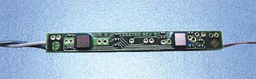 Photo 1. The small CSP chip at the left end of the PCB converts the analog signal from the thermocouple (off to the right) into a digital 1-Wire signal. The thermocouple is the small-gauge wire on the right. The actual size of the board is 1.75 in. by 0.20 in. |
The chip can directly digitize the millivolt level output produced between the hot and cold junctions, while its onchip temperature sensor continuously monitors the temperature at the cold junction. The unique ID address provides a label that permits multiple units to operate on the same twisted-pair cable. And it contains user-accessible memory for storage of sensor-specific data such as thermocouple type, location, and the date it was put into service [5]. This allows a DS2760 to be used with any thermocouple type because the bus master uses the stored data todetermine the correct calculations to make, based on the type of thermocouple in use and the temperature of the cold junction as reported by the onchip temperature sensor.
A complete signal conditioning and digitizing solution for use with a thermocouple, the DS2760 contains a 10-bit voltage ADC input, a 13-bit temperature ADC, and a 12-bit plus-sign current ADC. It also provides 32 bytes of lockable EEPROM memory where pertinent user or sensor documentation may be stored, minimizing the probability of error due to sensor mislabeling.
In the present application, the thermocouple is directly connected to the ADC current inputs that were originally designed to read the voltage drop developed across a 25 mω resistor as a lithium ion battery pack is charged and discharged. With a full-scale range of ± 64 mV (LSB of 15.625 µV), the converter provides resolution better than 1°C, even with the lower output of a type K thermocouple.
Measuring a Thermocouple over the 1-Wire
Figure 4 illustrates both the simplicity and ease with which a DS2760 can be used to convert a standard thermocouple into a smart sensor with multi-drop capability.
 Figure 4. The output from the 1-Wire thermocouple is digitized by a 12-bit plus-sign ADC. An onchip 13-bit temperature sensor provides cold junction compensation. CR1 and C1 provide power for the sensor. R1 allows reading the value of Vdd, but may be omitted if this function is not needed. |
In the circuit, C1 and one of the Schottky diodes in CR1 form a half-wave rectifier that provides power for the DS2760 by "stealing" it from the bus during idle communication periods when the bus is at 5 V. This is a discrete implementation of the parasite power technique used internally by 1-Wire devices to provide their own operating power. The remaining Schottky diode in the package is connected across DATA and GND and provides circuit protection by restricting signal excursions that go below ground to about –0.4 V.
Without this diode, negative signal excursions on the bus >0.6 V forward bias the parasitic substrate diode of the DS2760 chip and interfere with its proper functioning. Under bus master control, U1, the DS2760, both monitors the voltage developed between the hot and cold junctions of the thermocouple and uses its internal temperature sensor to measure the cold junction temperature. The master uses this information to calculate the actual temperature at the hot junction. Adding the optional resistor (R1) allows the voltage available at Vdd to be measured as well. In troubleshooting this can be useful to verify that the voltage available on the 1-Wire net is within acceptable limits.
When mounting the thermocouple to the board, care should be taken to connect it as close as practical to the DS2760 so that minimal temperature difference exists between these connections and the chip inside the DS2760 package. To maintain the junctions at the same temperature requires the use of copper pour and lead placement to create an isothermal area in and around the point where the thermocouple leads attach to the copper traces of the PCB. Because temperature differentials generate voltage differentials, the PCB traces should be routed together and equal numbers of junctions maintained on each conductor.
Summary
This article has described the way to combine a standard thermocouple with a DS2760 lithium ion monitor chip to convert it into a smart sensor that communicates with a PC or microcontroller over a single twisted-pair cable. This cable, which serves to cover the distance between the thermocouple and bus master, effectively replaces the expensive thermocouple extension cable normally used. The chip digitizes the millivolt-level signal produced between the hot and cold junctions of two dissimilar metals at´a given temperature due to the Seebeck effect, and communicates all necessary information to the local host so that the correct temperature at the hot junction may be calculated.
The onchip temperature sensor continuously monitors the temperature at the cold junction to minimize reference errors. In addition, the onchip memory can store the thermocouple type and when and where it was placed into operation, which can minimize the probability of error due to the mislabeling of sensors. This information allows a DS2760 to be used with different thermocouple types because the bus master reads the stored data to determine the correct calculations to use based on the type of thermocouple and the cold junction temperature as reported by the onchip temperature sensor. Finally, due to the unique ID address that all 1-Wire devices possess, multiple smart thermocouples may be placed where needed anywhere along the net, greatly minimizing the positioning and cost of an installation.
1-Wire and 1-Wire net are trademarks of Dallas Semiconductor.
References
1. Dan Awtrey. Feb. 1997. "Transmitting Data and Power over a One-Wire Bus," Sensors:48-51.
2. ____. "1-Wire Net Design Guide."
3. "Using Thermocouples." [PDF]
4. DS2760 Data Sheet. [PDF]
5. Tagging protocol. [PDF]